Genetec
Introduction
This manual provides an overview of Scylla Alarm Receiver plugin for Genetec Video Management System (VMS) and instructions on how to use it.
This plugin adds additional functionality to Genetec Video Management System to support Scylla AI Modules.
Scylla has two-way fully integration with Genetec Security Center alarm management system which means that it takes input from Genetec Server and reports back to Genetec Security Desk.
Scylla Alarm Receiver Setup
Scylla Alarm Receiver setup file for Genetec can be downloaded from Scylla's Cloud Dashboard.
Navigate to Account Settings à Resources à alarmreceiver à select the latest version
NOTE: Scylla Alarm Receiver can be installed on the Genetec Server or separate server with connection to Genetec Server.
Prerequisite:
-
.Net Framework 4.8
-
.Net Runtime 6.0
-
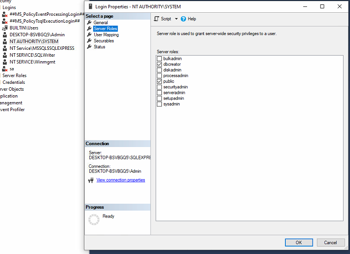
MS SQL Express with Local System Account having the dbcreator role enabled
-
Security Desk application
Right click on the Local System Account -> Properties -> Server Roles and enable dbcreator
To setup Scylla Alarm Receiver do the following:
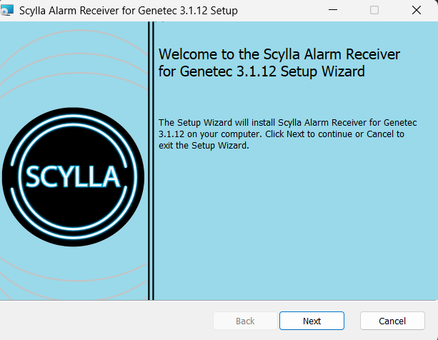
- Open the ScyllaAlarmReceiver.Genetec.Setup.msi file. Click Next.
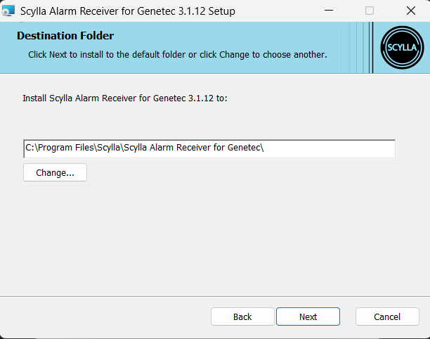
- Specify the installation path. For example, C:\Program Files\Scylla\Scylla Alarm Receiver for Genetec\ Click Next.
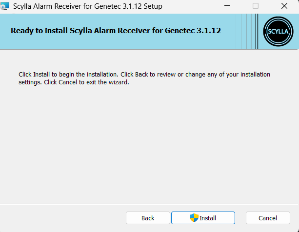
- Click Install.
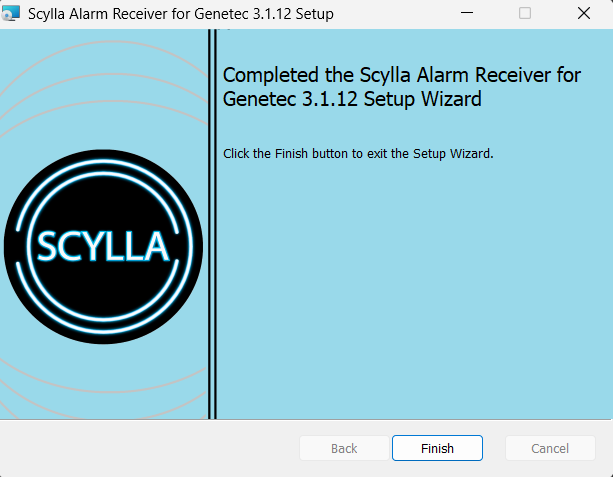
- Click Finish.
Configuring Scylla Alarm Receiver
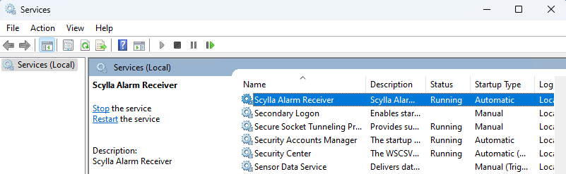
Navigate to Services and start Scylla Alarm Receiver service.

Fill the Server Credentials
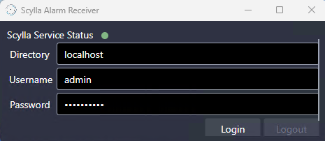
Enter Genetec Server credentials and click Login.
After Successful connection to the server, new configuration fields will be displayed.
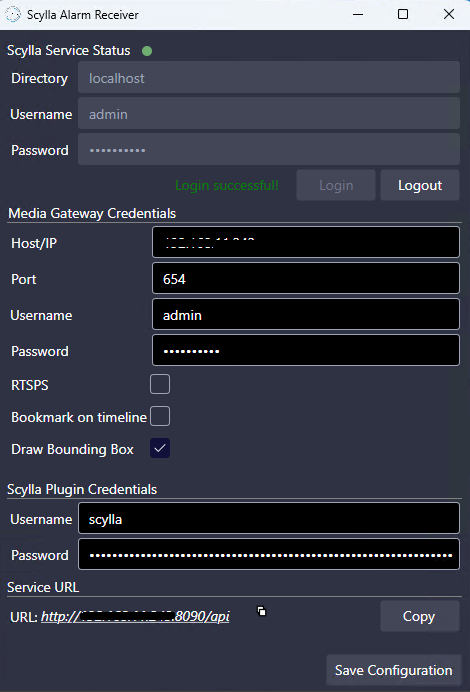
Fill the Media Gateway Credentials
Host/IP: IP address of the Media Gateway
Port: Listening port configured in the Media gateway properties in Genetec Config Tool
Username & Password: Credentials for Media Gateway, if in the Media gateway properties page the User authentication is off, use the Server credentials.
If User is created in Media Gateway properties page, use those credentials.
The above fields are populated based on the Media Gateway Role in
Genetec config tool -> System->Roles->Media Gateway->Properties
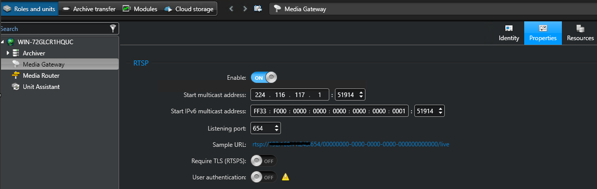
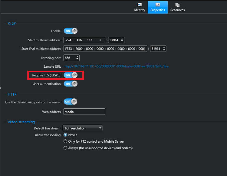
RTSPS : Should be enabled only when the "Require TLS (RTSPS)" option is enabled in the Media Gateway role.
Bookmark on Timeline : Enabling this will create automatic bookmarks on Genetec when alarms are received from Scylla . These bookmarks are shown on timeline and also in Bookmarks task.
Draw Bounding Box : Enabling this will display the bounding box around the detection in live & playback modes.
Important Notes
- Drawing on a camera connected via an RTSP stream is not possible; the camera must be connected through SDK integration.
- The live and recording resolutions must match; otherwise, inaccuracies may occur when viewing data live.
- If the camera resolution is changed, you must restart the Scylla Alarm Receiver Service for the changes to take effect.
- Some AI Modules may send shifted timestamp, so delays may occur in recording, and you might miss the box on live stream. Drawing on a camera connected via an RTSP stream is not possible; the camera must be connected through SDK integration.
The live and recording resolutions must match; otherwise, inaccuracies may occur when viewing data live.
If the camera resolution is changed, you must restart the Scylla Alarm Receiver Service for the changes to take effect.
Some AI Modules may send shifted timestamp, so delays may occur in recording, and you might miss the box on live stream.
Possible causes: camera latency, networking latency, processing latency (application side), sending VMS latency (time sync is crucial).
Fill the Scylla Plugin credentials
Username & Password: Set username and password that will be used in the Scylla Asteria or Scylla On-premise dashboard Integration configuration page to establish a connection.
Click Save.
Click Save Configuration.
Scylla Dashboard Configuration
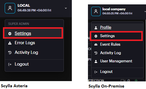
Open the Scylla Asteria or Scylla On-Premise Dashboard.
Go to Account menu -> Settings
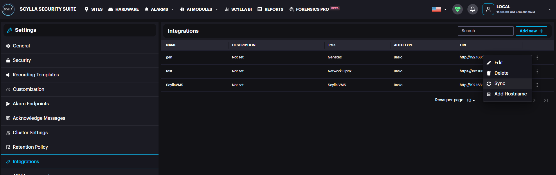
Now navigate to Integrations menu
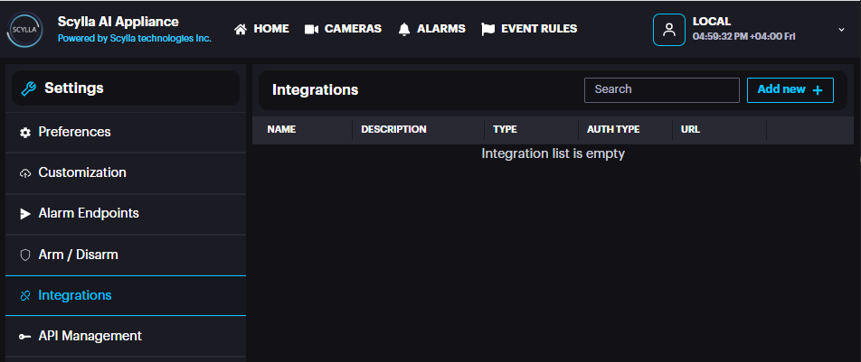
Click Add new +
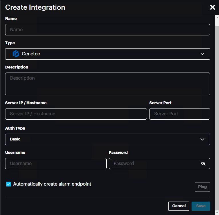
Name: name the integration
Type: Select Genetec from the list
Description: Add a description if needed
Server IP/Hostname: IP address of the Genetec Server/Scylla Alarm receiver
Port: 8090
Auth Type: Basic or Bearer (select Basic)
Username: username that is set in the Scylla Alarm Receiver -> Scylla Plugin credentials part
Password: password that is set in the Scylla Alarm Receiver -> Scylla Plugin credentials part
Click Ping to test the connection, if successfully connected then a message will be displayed.

Automatically create alarm endpoint: If enabled, an alarm endpoint will be automatically created in the settings-> alarm endpoints
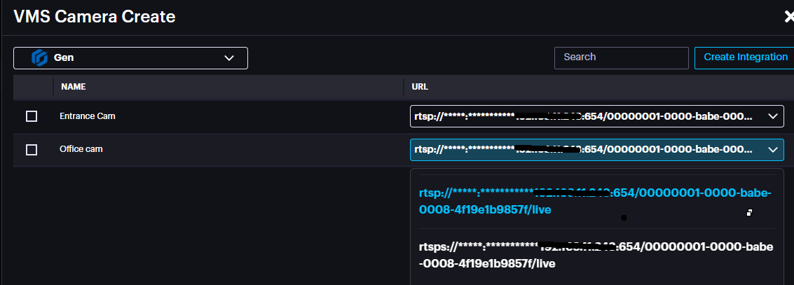
Importing Cameras from VMS
Scylla Asteria
Go to Cameras page and click add new +
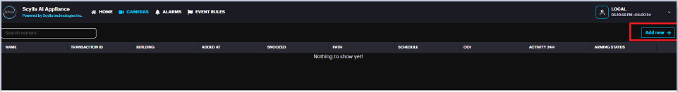
Select Import From VMS

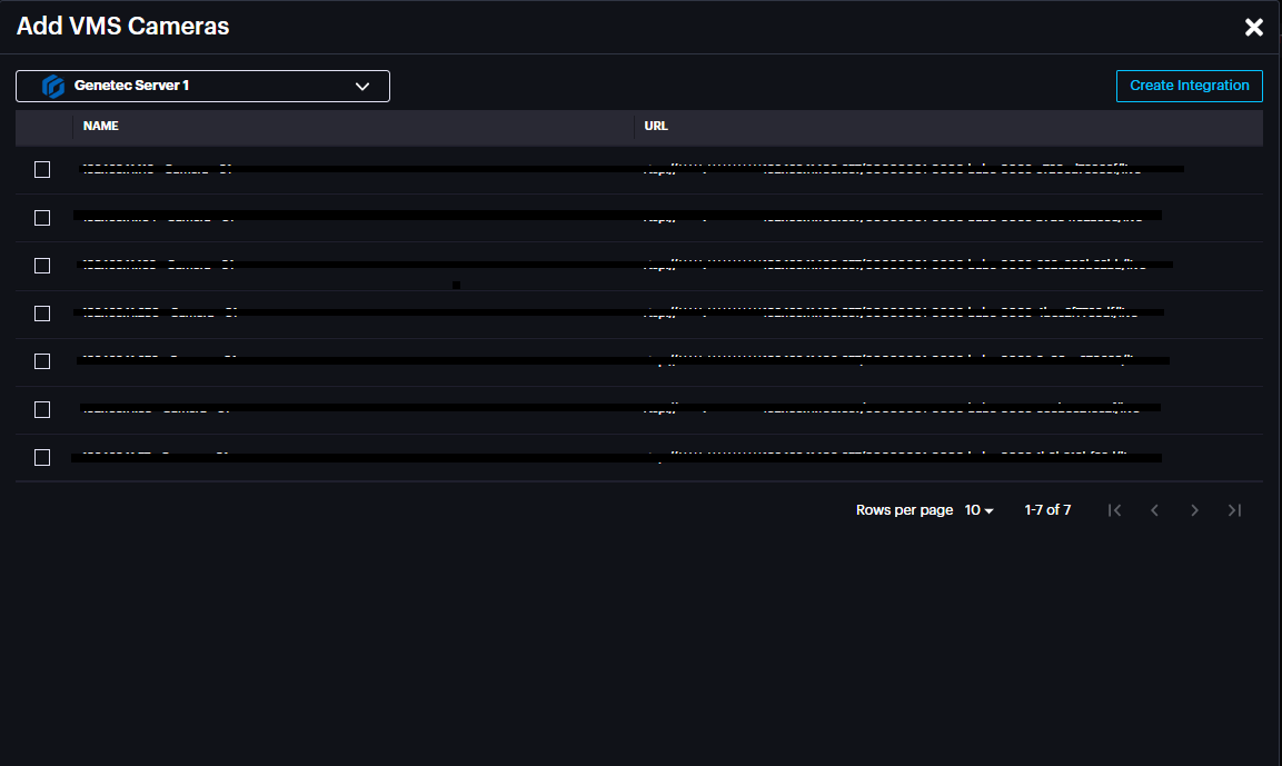
Select the Integration created previously from the drop-down menu.
Cameras from Genetec server will appear in this window, enabling the cameras to be imported to Scylla Asteria.
Click Create
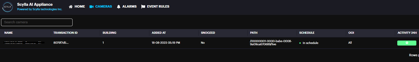
The imported camera(s) will be shown on the Cameras page.
Scylla On-Premise
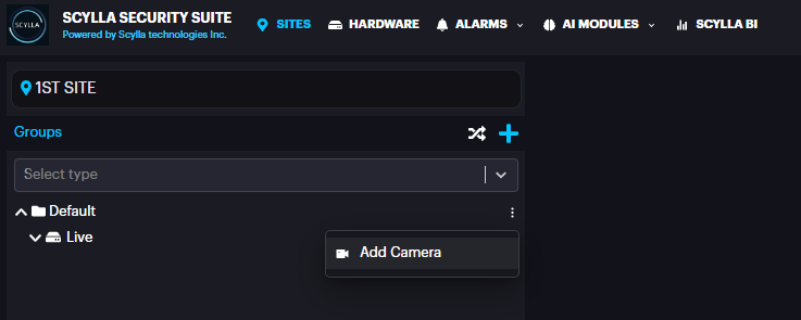
Go to Sites page, select a site -> Properties -> Manage Devices
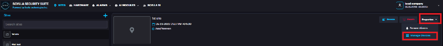
Click the three dots near the Group (Default) -> Add Camera
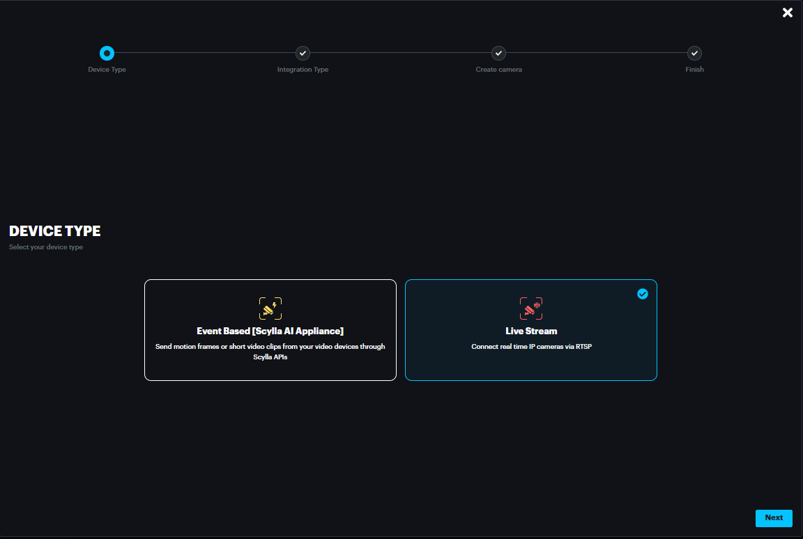
Select Live Stream and click Next
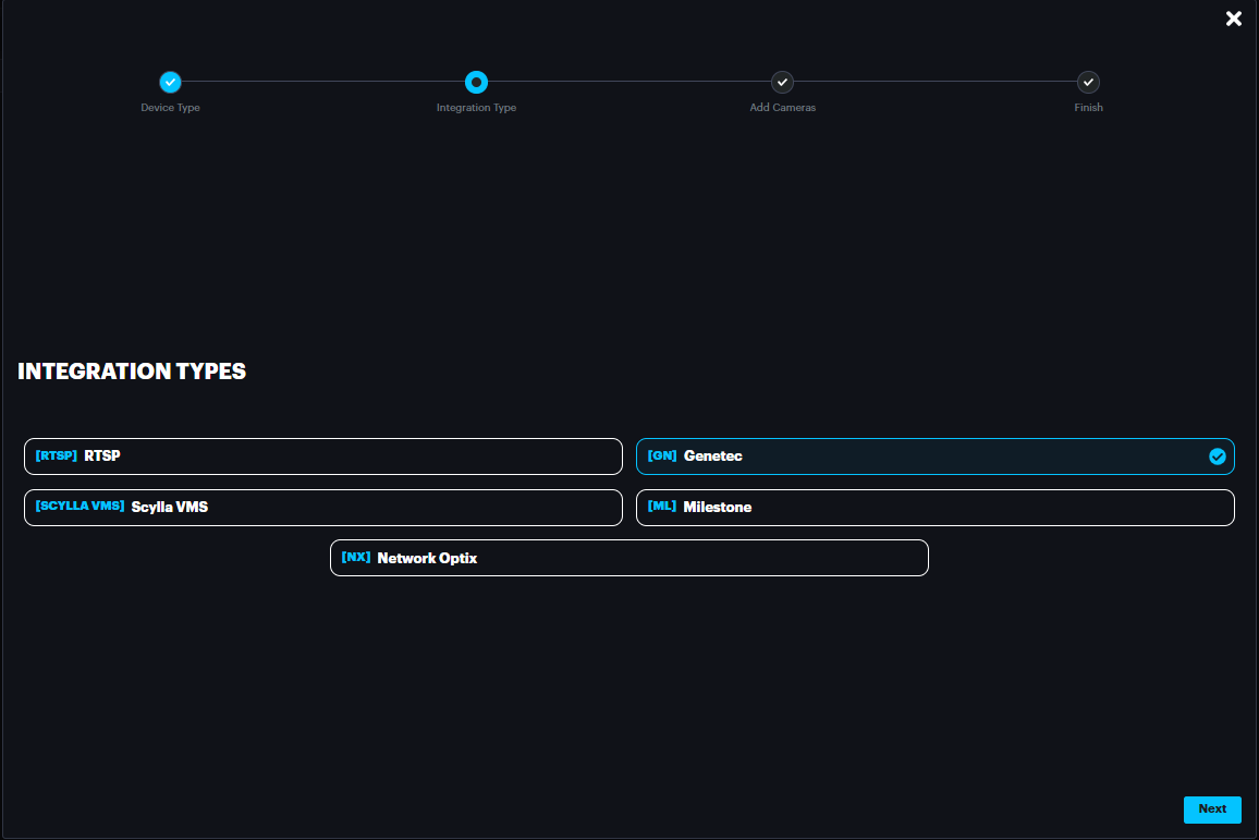
Select Genetec and click Next
Select the integration from the drop-down menu and the cameras on Genetec server will appear
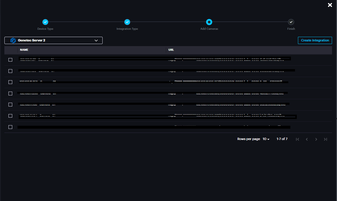
Enable the cameras that will be imported to Scylla on-premise server.
Click Create & Continue
The imported camera(s) will appear under the group

Once deployed, the alarms will appear on Scylla Dashboard and Genetec Security Desk
(alarm endpoint and event rule should be already configured).
Sync feature
If there are any changes to camera names in the VMS or if a camera is removed from the VMS, use the sync feature to update these changes on the Scylla dashboard.
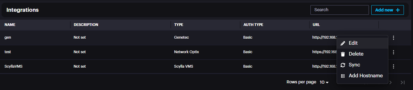
Navigate to Settings à Integrations à three dots à Sync
Add Hostname
If the Genetec Media Gateway IP address changes, the "Add Hostname" feature lets you update the Media Gateway's IP address. This will automatically refresh the IP in the RTSP URL for all existing cameras from Genetec in one click, preventing any disconnection.
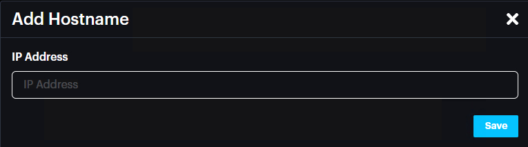
Enter the new Media Gateway IP address and click Save.
RTSPS Configuration (if required)
Genetec RTSPS Configuration
Go to Media Gateway -> Properties and enable RTSPS
Scylla Dashboard RTSPS Configuration
When adding the cameras from VMS , click on the drop down menu and the RTSPS URL will appear.
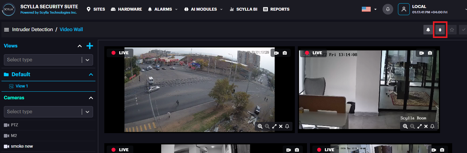
Deployment
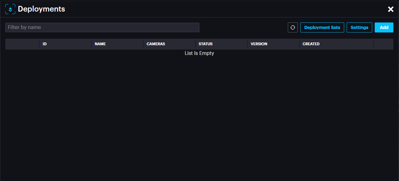
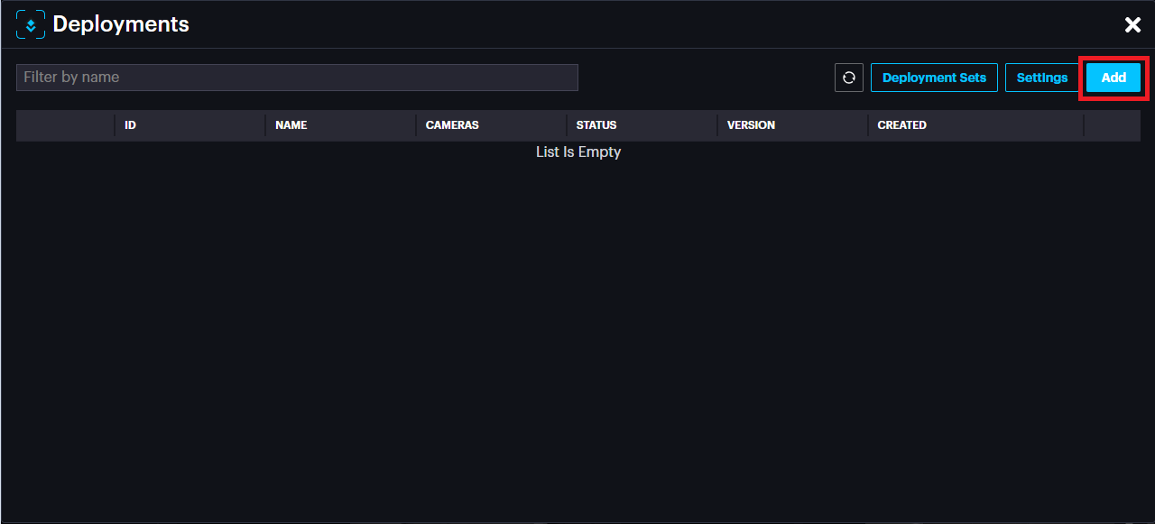
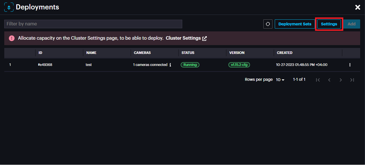
To add a new deployment , go to AI MODULES section and select the required AI Module. Then click the Deployments icon
Deployments pop up appears, click Add.
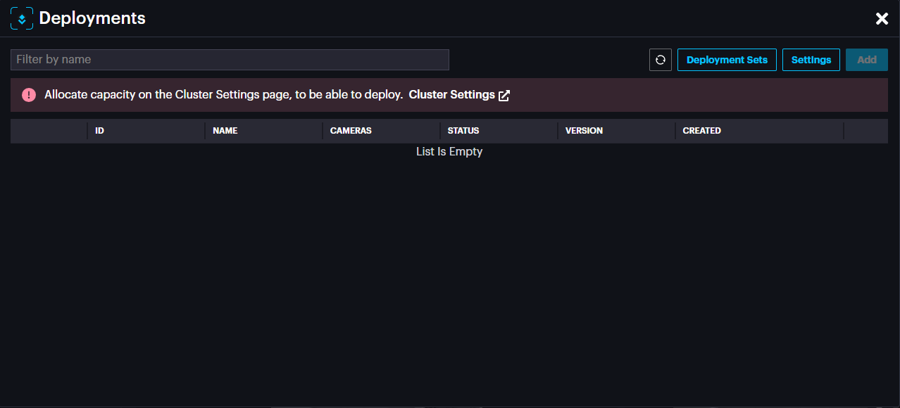
If you have not allocated capacity for this module, a message will appear.
Click on Cluster Settings to navigate to Settings->Cluster Settings.
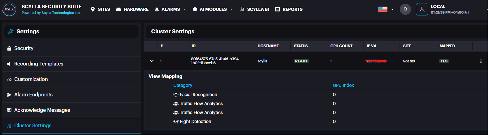
Here, Cluster information appears with number of GPUs installed (under GPU count)
And a summary about the modules/gpu mapping.
If you have several GPUs installed, you can balance the load by distributing the modules across several GPUs.
Click on the three dots in the cluster record then GPU Mapping.

Now the list of modules with their GPU mappings appears, if any.
You can add mapping by clicking +.
After selecting module and mapping to the GPU index, click submit.
Now you are ready to add deployment.
Back to deployments page, it is possible to create Deployment sets to assign cameras to sets and save them to avoid camera selection every time manually.
Click Deployment Sets
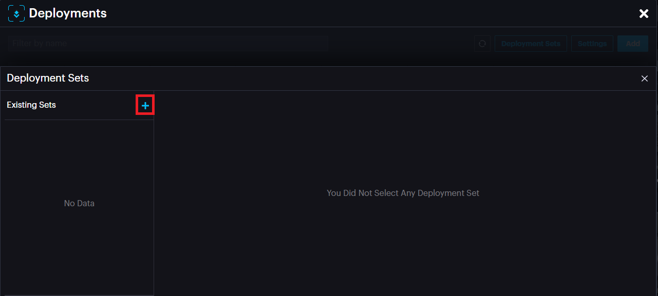
Click the add button to add a Set.
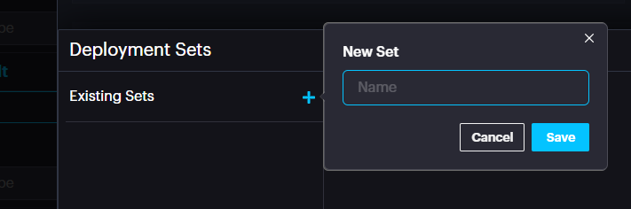
Name the Set. Click Save.
List of available cameras and selected cameras appear.
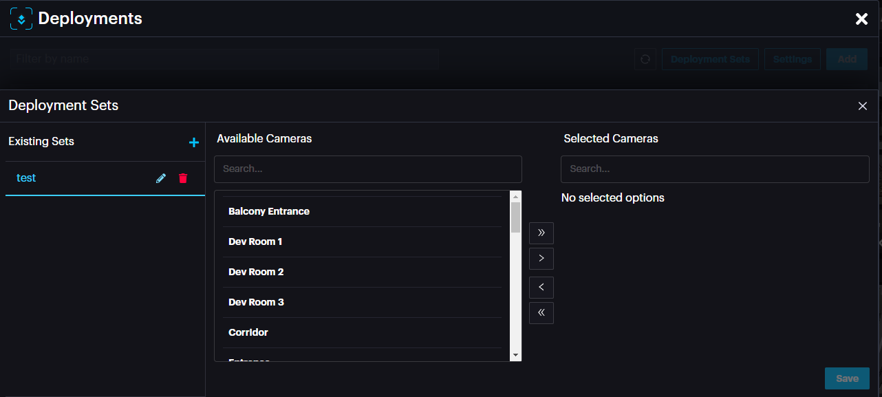
Choose the required camera(s) and drop them in the Selected cameras window by clicking the > arrow.
It is possible to remove cameras from a set by selecting the camera and clicking < arrow.
After adding the camera(s) to a set, click Save.
Now click on the add button to add deployment.
A new deployment window appears.
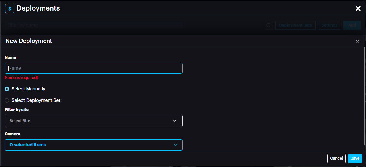
Name: Name of deployment
Select Manually: Select the cameras manually from the camera drop down menu below.
Select Deployment Set: select Deployment set if you have already created one.
After selecting the camera(s) or set, click Save.
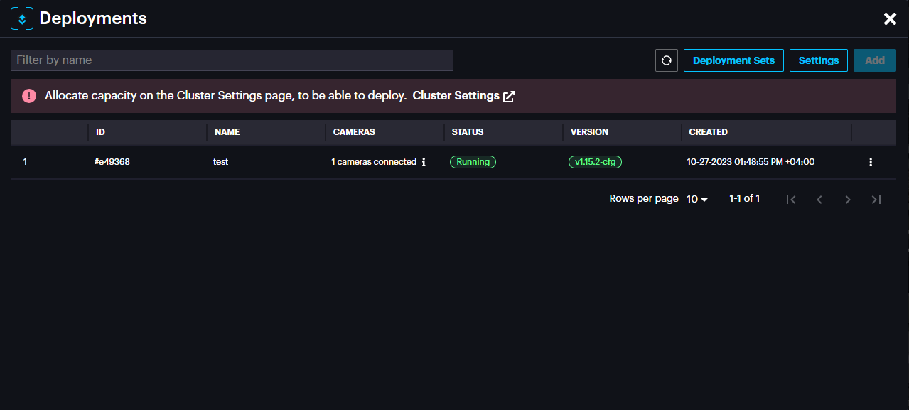
The new deployment will appear with the status (Pending, Waiting or Running).
In the deployment window, click Settings to access configuration specific to the module.
The settings page includes settings specific to the module such as threshold, cooldown between detection, etc. Change these settings carefully as it will affect the detection rate.
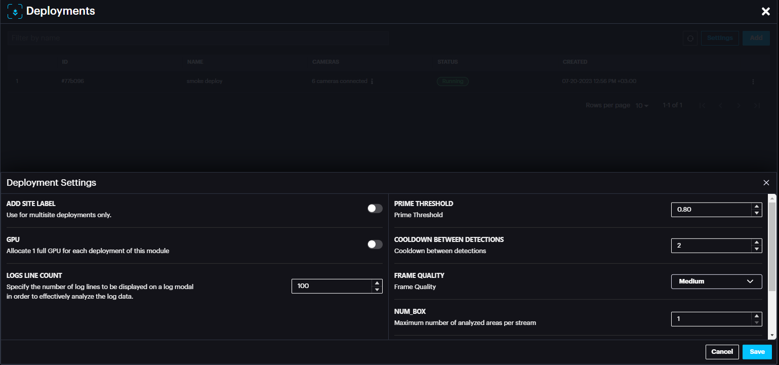
In case of any setting change, click Save.
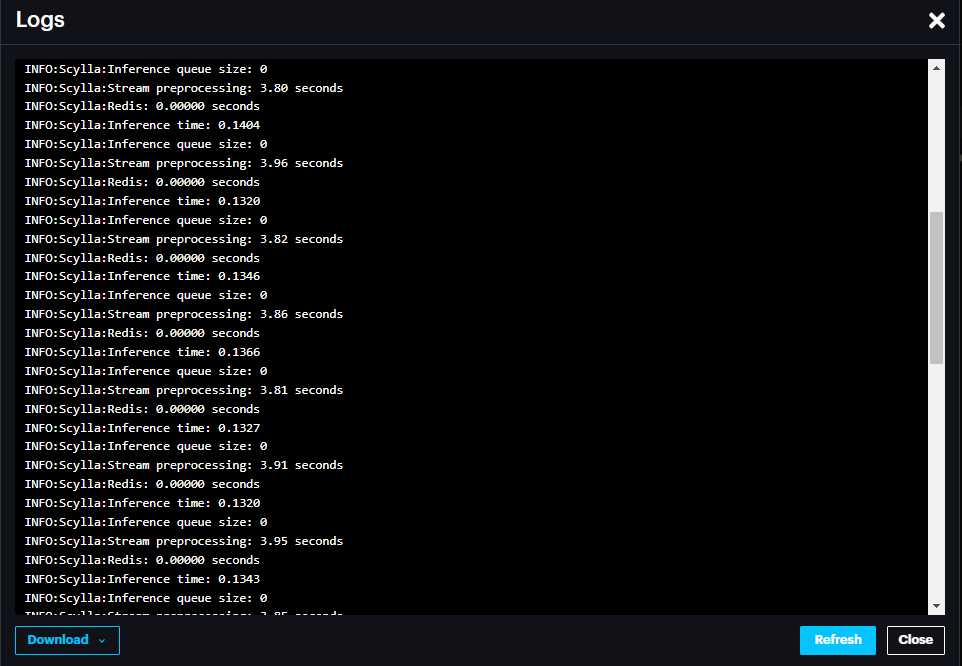
For successful deployment, the deployment status should state Running (usually in few minutes after adding deployment). You can refresh the page by clicking the refresh button on the top right of the window.
In case the status is not changed to Running, it is possible to check the logs by clicking more options (three dots) then View Logs. In the Logs window it is possible to Download the logs from the bottom left section.
It is possible to Restart the deployment, edit deployment or Delete deployment by clicking the three dots at the end of the record.
Configuring Event Rules
Event rules are created to link the events, schedules, and actions.
Scylla Asteria
Go to EVENT RULES page click Add
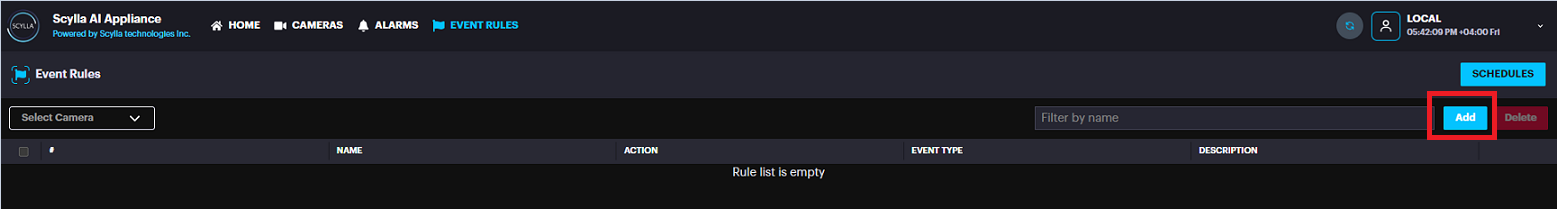
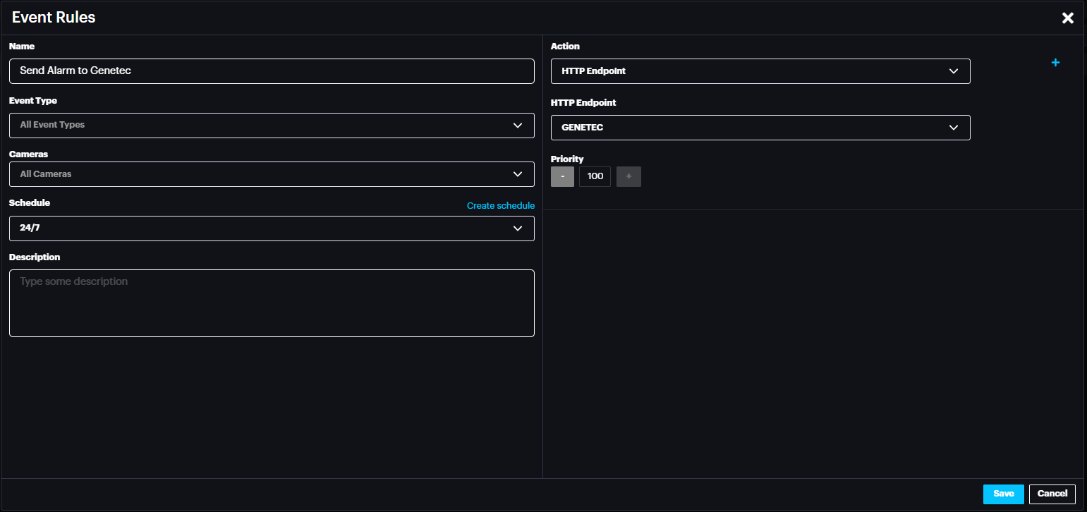
Name the event rule, select the event type (default is All event type), Select the camera(s) whose event will trigger the action (default is All cameras), select schedule (select the default 24/7 from drop down menu or create new schedule by clicking create schedule).
In the action select HTTP Endpoint and for HTTP Endpoint select GENETEC.
Click Save.
Now click Apply configuration on top.
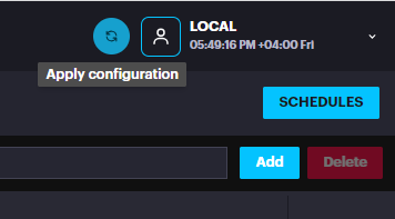
Now Scylla Asteria is ready to send the alarm to Genetec Security Center from camera(s) that are configured in the Event Rule.
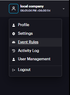
Scylla On-Premise
Go to Account Menu -> Event rules
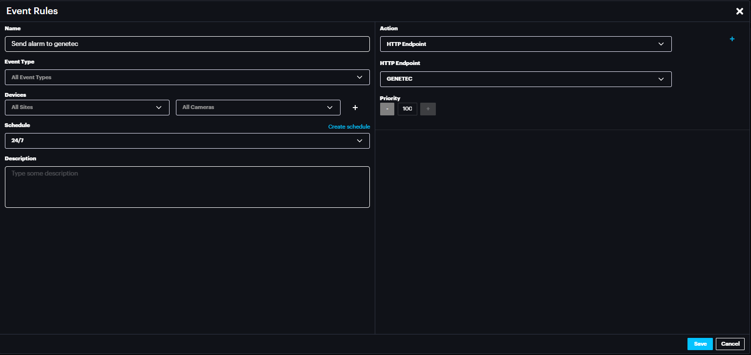
Name the event rule, select the event type (default is All event type), Select the Site and camera(s) whose event will trigger the action (default is All Sites & All cameras), select schedule (select the default 24/7 from drop down menu or create new schedule by clicking create schedule).
In the action select HTTP Endpoint and for HTTP Endpoint select GENETEC.
Click Save.
Now Scylla On-Premise is ready to send the alarm to Genetec Security Center from camera(s) that are configured in the Event Rule.
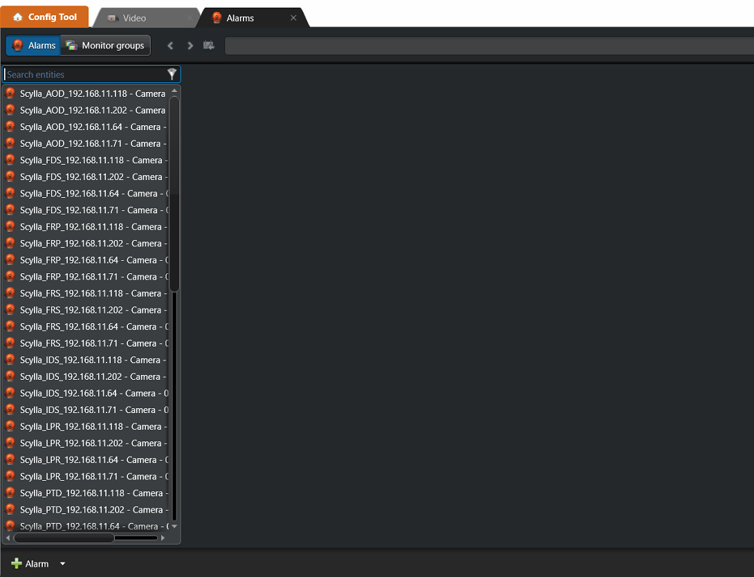
Genetec Config Tool
When creating Genetec integration and importing cameras from Genetec, alarms are created for all those Genetec cameras based on the available modules on the Scylla Dashboard. Existing alarms in Genetec config tool remain untouched.
Alarms can be edited (name, description, recipients), and changes will not be overwritten later
By default , recipients are empty.
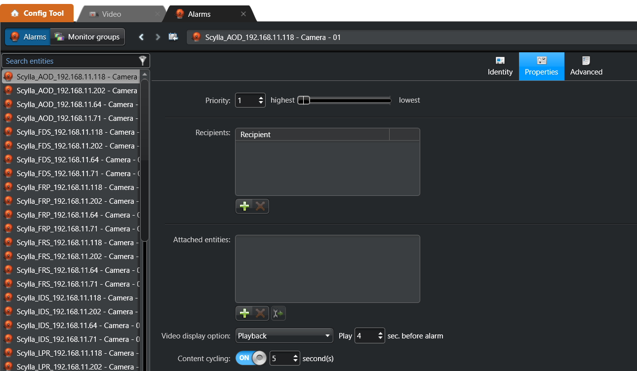
This is to allow the users to define the recipients of each alarm and provide flexibility to choose different recipients for different Alarms.
For optimal efficiency, define recipients by creating User Groups within the User Management section
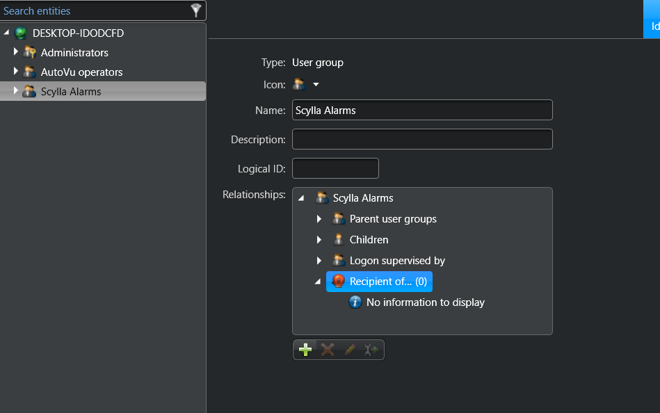
Once the User Group is created, add the desired members to it. Navigate to the Recipients menu on the right-hand sidebar and click the Add (+) button to link the group to the specific alarm(s).
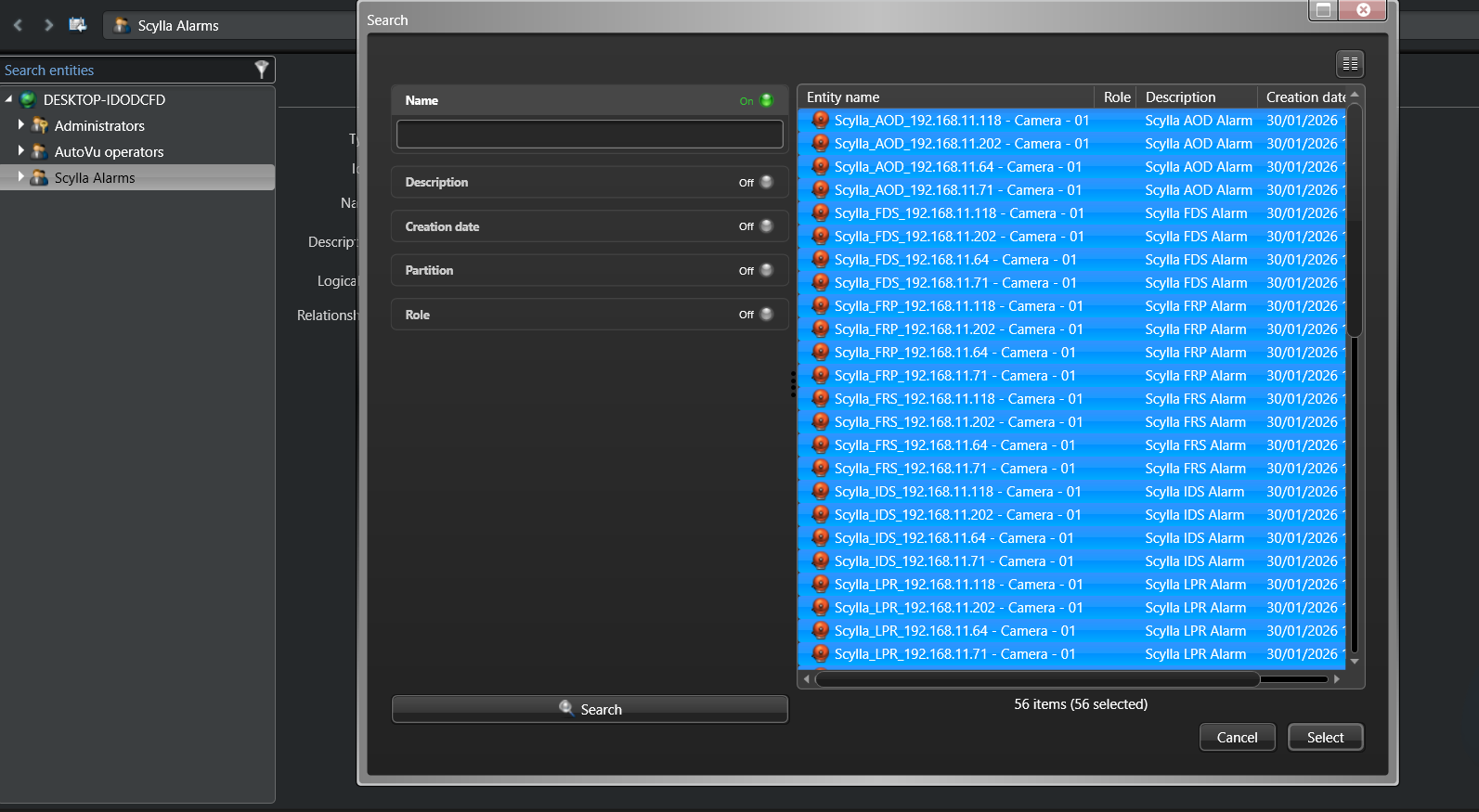
Select the alarm(s) related to this user group and click select.
Genetec Security Desk
Alarm Monitoring
In the Alarm Monitoring task, alarms from Scylla will appear with information including the alarm source (camera name), the type of alarm (such as intrusion:IDS, Gun:PTD, Face recognition: FRS and more), and the probability of detection.
Additionally, the alarm video is displayed (playback, Live and playback etc.) based on the Alarm settings in the Config tool.
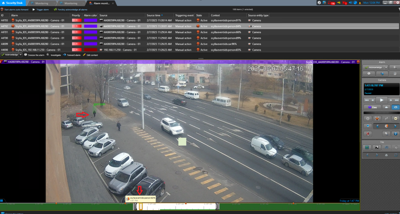
If "Draw Bounding Box" is enabled in the Scylla Alarm Receiver interface, the alarm video will display a bounding box at the detection location.
Furthermore, if the "Bookmark on Timeline" option is enabled in the Scylla Alarm Receiver interface, bookmarks will appear on the timeline with detailed alarm information.
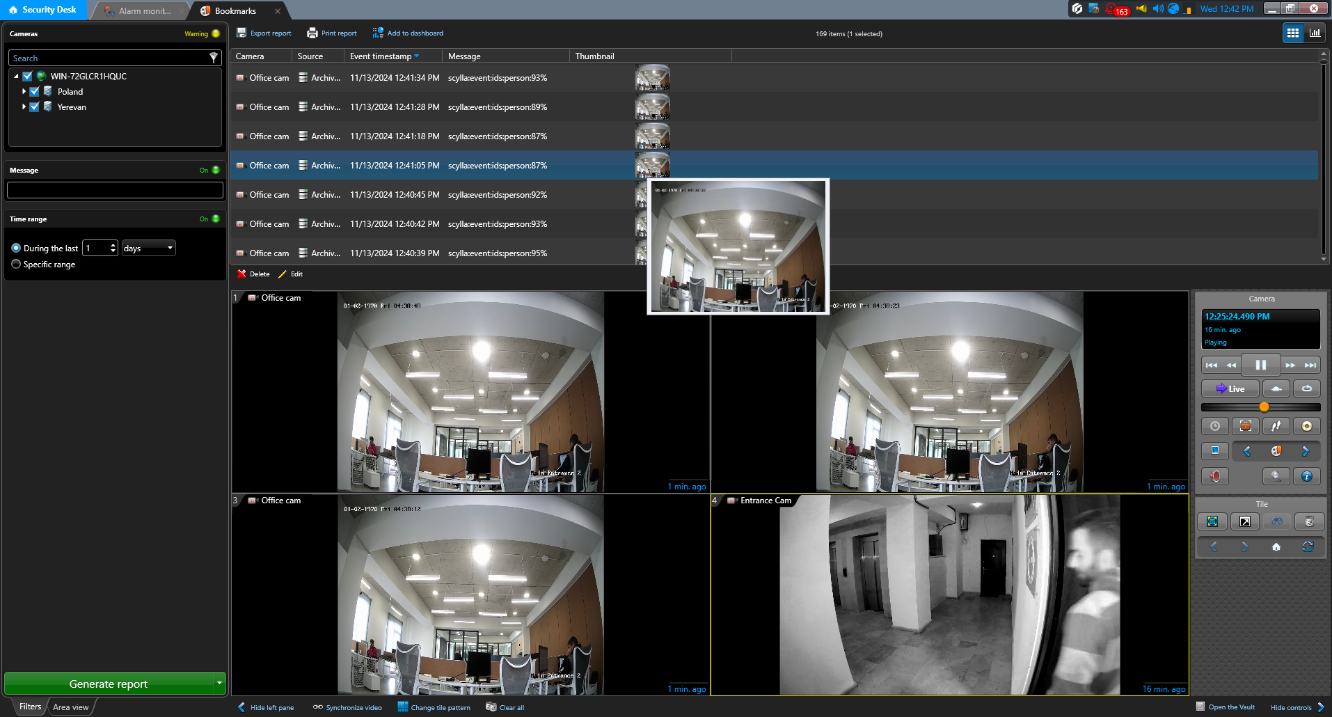
Bookmarks
In the Bookmarks task, you can generate a report of the bookmarks. A list of automatically created bookmarks appears at the top, each with detailed information and a thumbnail (screenshot of the alarm). Clicking on a bookmark will display the video recorded at the bookmark time which is equivalent to alarm time.
The report can also be exported from the top menu in Excel, CSV, or PDF format.
We value and appreciate your feedback. If you have any questions or suggestions, please contact support@scylla.ai or submit a request to the Scylla Help Center at https://support.scylla.ai/portal/en/home.