User Manual
Introduction
This manual provides an overview of Scylla Asteria™ Vanguard and instructions on how to set it up and use it.
At Scylla, we utilize AI and computer vision to detect objects, actions, and behavior anomalies. Scylla AI-powered solutions serve to improve every part of your security infrastructure and range from object detection, anomaly detection & behavior recognition, to perimeter intrusion detection, facial recognition, and drone security. We expanded our product offering and included Scylla Asteria Vanguard, a smart edge monitoring solution. It’s specifically designed to provide small-scale installations with advanced AI-powered functionality. The greatest thing about it is that it’s compact enough to sit on a shelf and is cost-effective, which is particularly great for small businesses and homeowners. This would help even more customers to bolster their security and better protect their people and property.
When the detection occurs, Scylla sends a real-time alert with a photo of the detection to your mobile device or VMS. It adequately protects facilities by detecting intruders using existing security cameras, eliminating the need for new hardware, and saving you money and time.
Whether you monitor, install, or manufacture CCTV, Scylla is here to help you to detect and potentially prevent crimes using the most accurate, fast and human-factor free AI analytics.
With Scylla's AI-powered analysis, you can get real-time security alerts from your cameras. Use your dashboard to define monitoring zones, schedule alerts, and view live or recorded video anytime.
General
Scylla Asteria Vanguard operates on-premise, using your local infrastructure for edge processing. When connected to the cloud, you can manage alarms and view live and recorded streams through the Scylla Cloud Dashboard.
Scylla Asteria Vanguard can be fully managed using the Scylla AI mobile app, available for both Android and Apple iOS devices.
Scylla Asteria Vanguard dedicated Web Dashboard is password-protected, so you must log in by providing your user credentials (username/password) to access the dashboard.
Warnings and Restrictions
ATTENTION! Please note that Scylla Asteria™ is equipped with a passive cooling system. That means that during the installation and operation Scylla Asteria™ can heat up to approximately 65℃.
The device requires observation and caution during the installation. The device should not be installed near inflammables.
Login
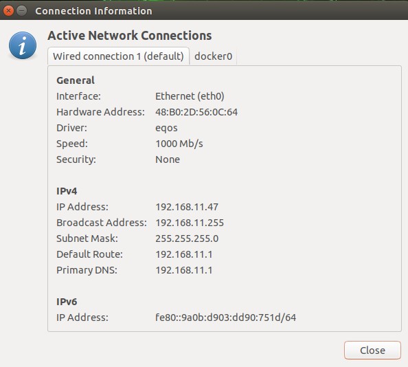
After connecting the Scylla Asteria™ Vanguard to the local network, you must find the IP address of the
device. There are two ways to do that.
![]()
The second way is to download and install the free tool of Advanced IP Scanner from https://www.advanced-ip-scanner.com/.
Scan the network to get the available IPs in the network.
![]()
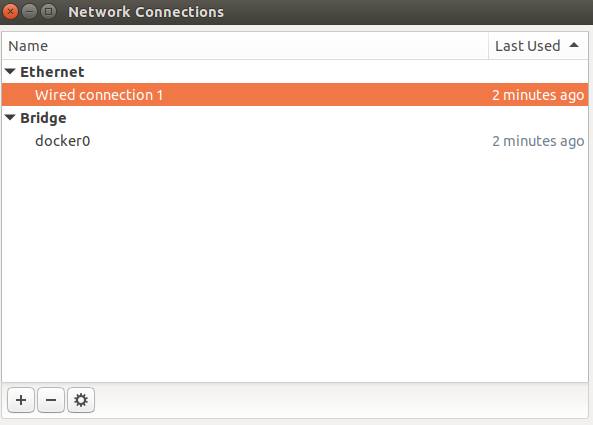
You can also find out how to find an IP address from the manual that comes with the device.
![]()
then click on Wired Connection, after Go to IPv4 Settings tab and you can change your IP settings to Manual, or DHCP, etc.
Now you can login into Asteria dashboard.
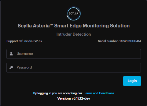
After you get the IPV4 address you can log in to the device dashboard from any PC in the local
network using the device’s IP (For example: http://192.168.11.123/login).
If you are already logged in, you will be redirected to the main Dashboard page.
If you are not logged in, you need to enter your Username and Password (admin/admin by default) into the corresponding fields and click the Login button.
NOTE. Please be attentive while entering your username and password into the fields. Make sure you have not copied any additional characters or left leading spaces.Example of leading spaces:Wrong: “ username” has leading spacesCorrect: “username” does not have any leading spaces.
After entering your credentials and clicking the Login button you will be redirected to the
Dashboard page.
If you are not redirected to the Dashboard page, there are two possible reasons:
- If you see the “Invalid credentials” message, that means you have entered wrong credentials. If you see the “Invalid credentials” message, that means you have entered wrong credentials.
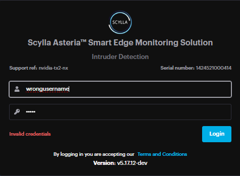
Double-check and reenter your credentials. If this message appears again, contact your administrator or change your password.
- If you are not able to log in and there is no message, try to clean your browser’s cache and try again. See this article for detailed instructions on how to clean your browser’s cache. If you are not able to log in and there is no message, try to clean your browser’s cache and try again. See this article for detailed instructions on how to clean your browser’s cache.
If cleaning the cache does not solve the problem, you are always welcome to submit a request on the Help Center.
Configuration and Integration
Camera Connection
You have two options to connect cameras to the Scylla Asteria™ Vanguard:
- Discover Cameras — which allows you to discover available cameras on your network
- Add Cameras Manually — which allows you to add camera manually Discover Cameras — which allows you to discover available cameras on your network
Add Cameras Manually — which allows you to add camera manually
Discover Cameras
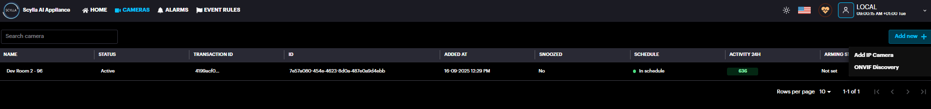
Or go to the Cameras menu and click on the Add new + -> ONVIF Discovery
You will see the list of available cameras on your local network.
To connect camera(s) from the list, select the checkboxes on the left of the desired camera(s) and click Connect Camera(s) button.
In the Connect Camera(s) pop-up menu specify the Name, Login and Password for the cameras. Click
Submit
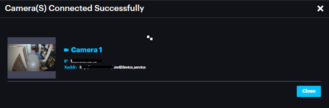
After successful connection the following screen will open. It will contain configurations of your chosen cameras.
Add Cameras Manually
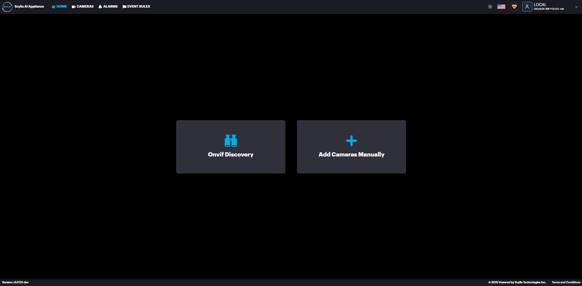
To add camera(s) manually, go to the Home Page and click the Add Cameras Manually button.
Or go to the Cameras menu and click on the Add new + -> Add IP Camera icon.
Create Camera window pops up , enter the Name and URL (RTSP link) of the camera. Click Connect.
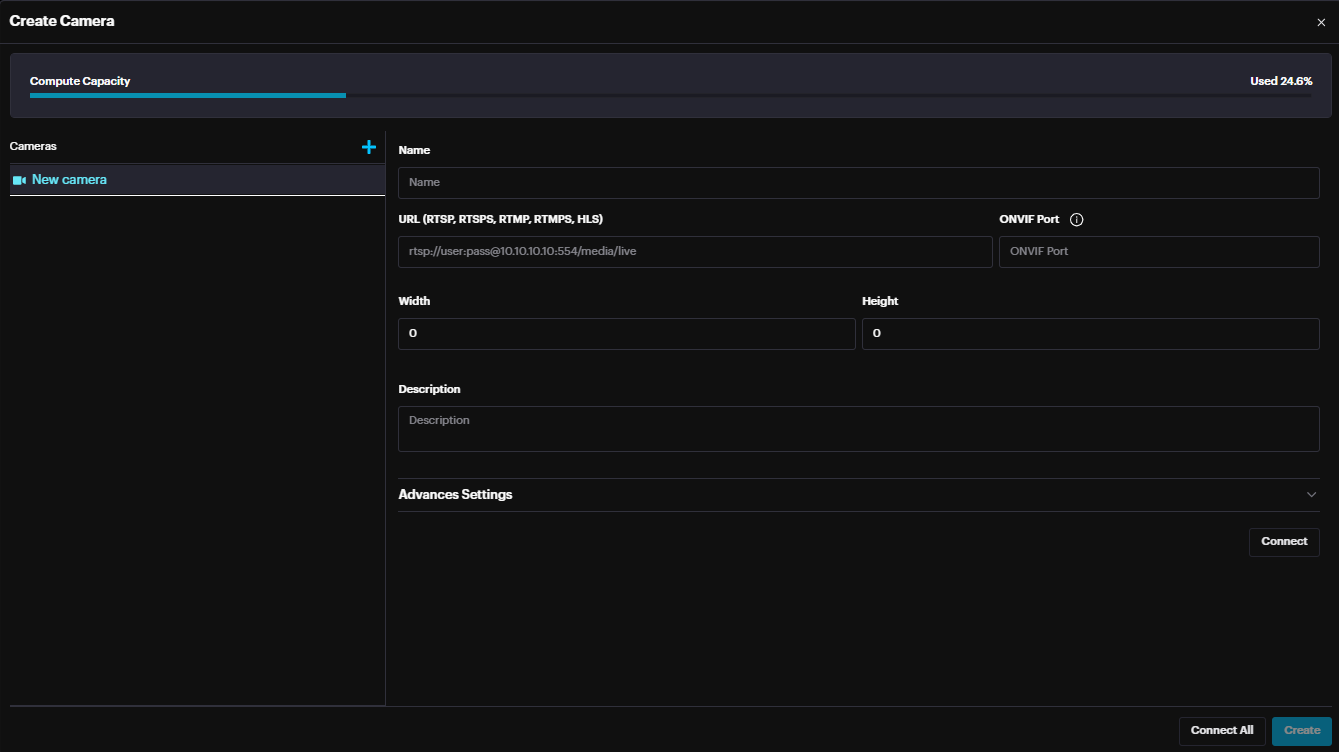
After a successful connection to the camera, width & height fields are automatically updated.
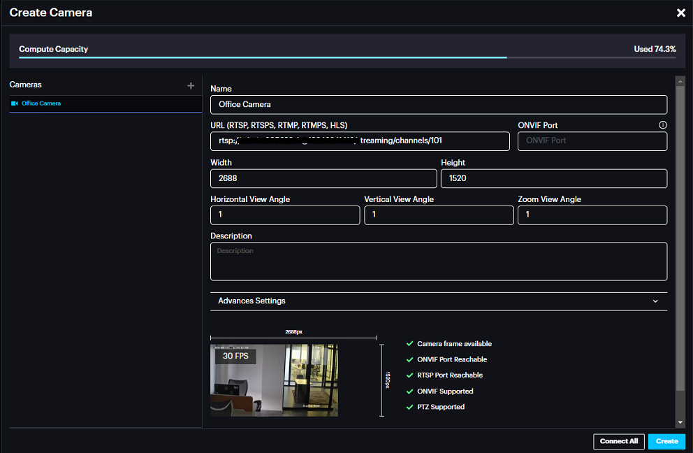
To add more than one camera, click the Add button, enter the Name and RTSP URL and click Connect.
After adding all the cameras, click Create.
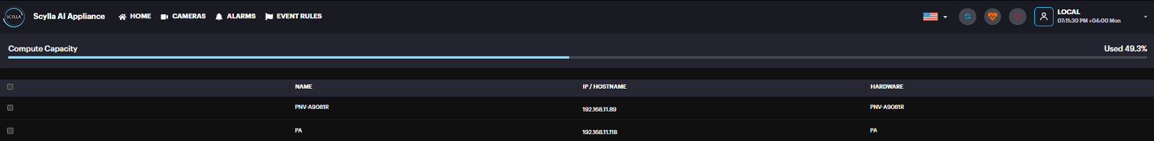
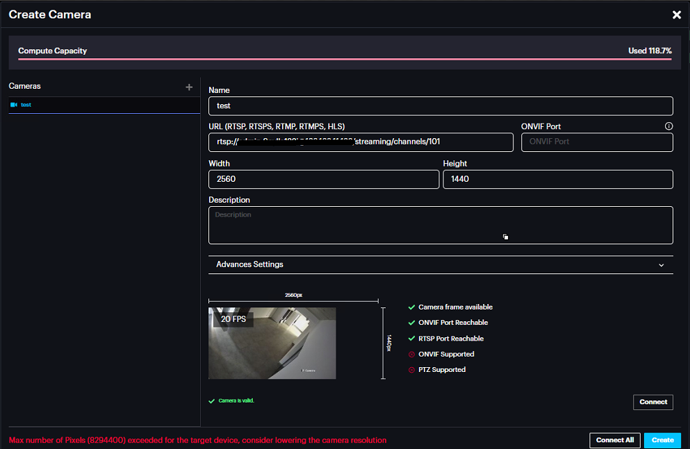
Compute Capacity at the top shows the percentage of compute capacity reached after adding the new camera.
If the Compute capacity passes the 100% then an error is displayed when creating the camera suggesting lowering the camera resolution since maximum number of pixels is exceeded for this Asteria.
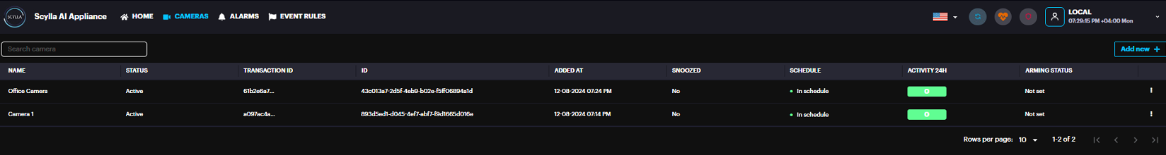
Now you can see the added camera(s) in the list.
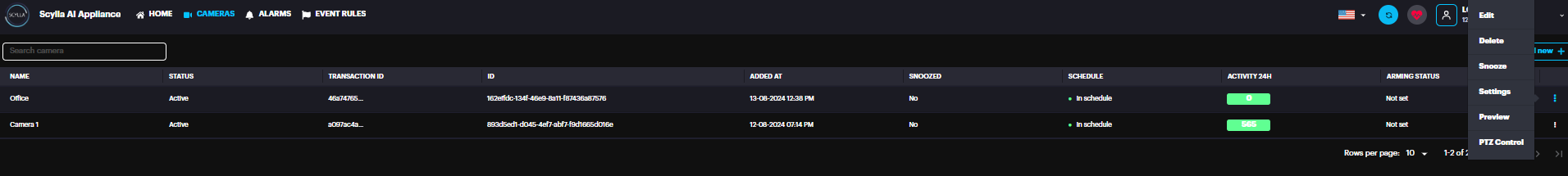
Camera Settings
Click on the More Options button to Edit, Delete, Snooze schedule, Preview or configure the camera’s settings
Edit Camera
Edit camera’s Name, URL, ONVIF Port.
Activate/Deactivate Camera using the toggle switch.
A screenshot of a computer
AI-generated content may be incorrect.
Click Submit.
Snooze Camera
If you want to snooze the camera’s schedule for a specific period, go to More Options →
Snooze schedule.
A black rectangular object with a black border
AI-generated content may be incorrect.
On the Snooze Schedule menu select the standard option (1 Hour, 2 Hours, 4 Hours).
Select Custom if you want to set a specific period. Then click on the Select date field and choose the desired date. Then click on the From and To fields to set a time range.
Click Submit.
Settings
To set up your camera according to your specific needs, go to camera’s
More Options -> Settings.
On the Coordinates section of the Update camera screen, you can draw the required coordinates for your camera by using your mouse (i.e., green rectangle on the door) or use the default section.
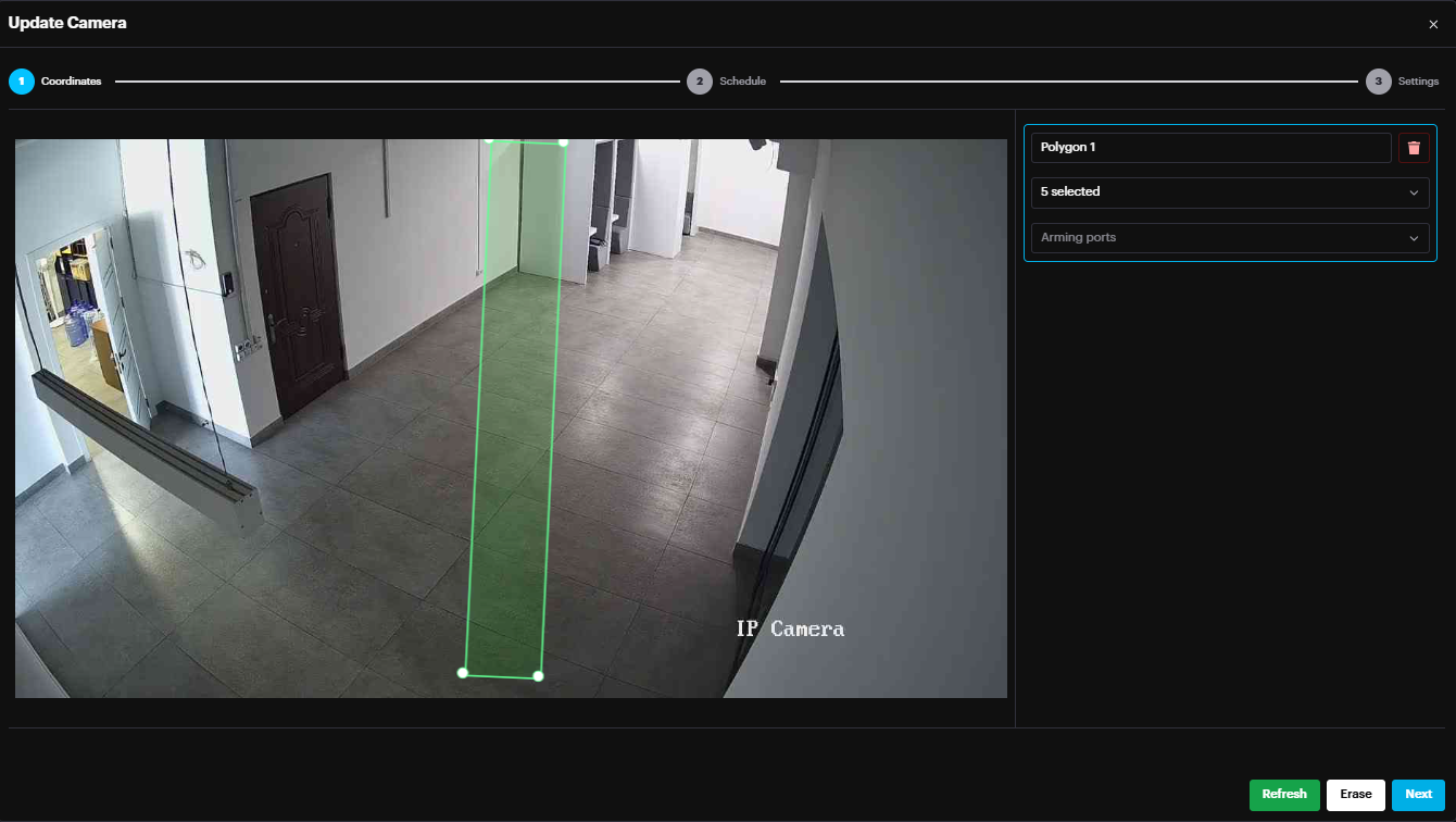
On the right menu Name the Area/Zone drawn.
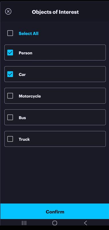
Select the OOI(s) per zone (Person, Car, Motorcycle, Bus, Truck).
Link it to Alarm input port (if used) to arm/disarm the Zone/Area.
To get more details about Arming/Disarming the Zone/Area, follow the Input Configuration section of this document.
Use the:
- Refresh button to refresh the streaming frame
- Erase button to erase the coordinates Refresh button to refresh the streaming frame
Erase button to erase the coordinates
Click Next.
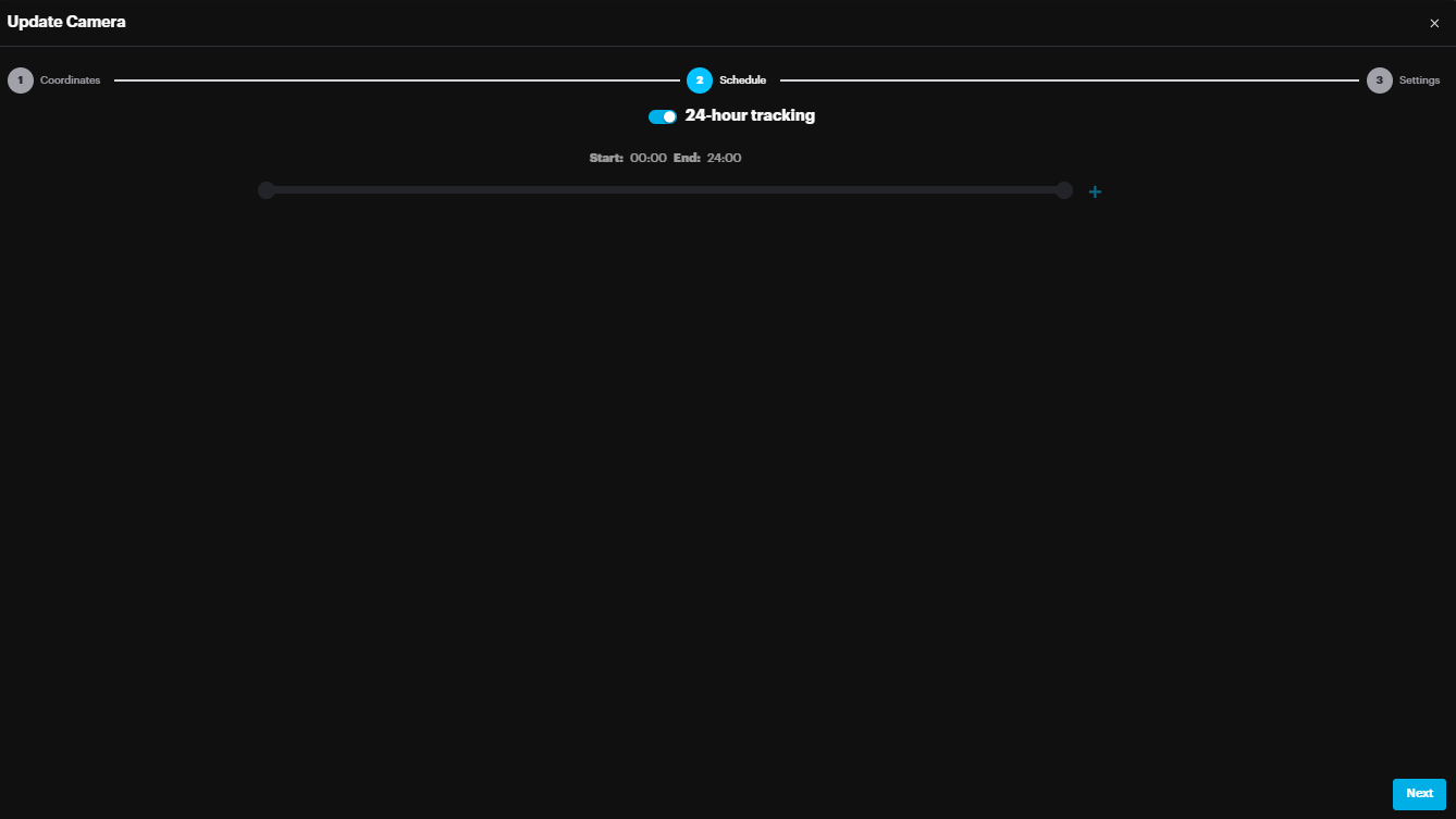
On the Schedule section you can specify the Start and End time of your camera’s tracking schedule. Drag the left point (Start time) and right point (End time) to the desired positions. Or enable the 24/7 Tracking toggle. Click Next.
In the Settings page, there is the Residential setting which is related to Intruder Detection module.
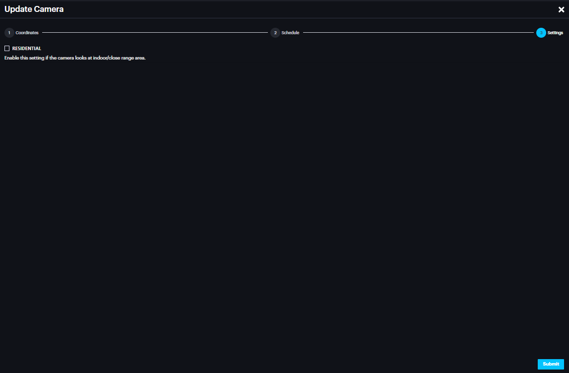
A "Residential" setting has been added to optimize detection accuracy and reduce false positives.
By default, this setting is OFF to maintain high sensitivity for long-range detection, but users can toggle it based on the following scenarios:
Outdoor Monitoring
Long-range monitoring (small intruders, 30-45 pixels): Keep the Residential setting OFF to detect distant objects.
Close-range monitoring (larger intruders, 50+ pixels): Turn the Residential setting ON to minimize false positives.
Indoor Monitoring
For indoor environments with generally larger objects, it is recommended to turn the Residential setting ON.
Summary:
Outdoor Long-range/Small objects: Residential = OFF
Outdoor Close-range/Large objects: Residential = ON
Indoor Monitoring: Residential = ON
Healthcheck
Healthcheck displays the status (normal, degraded, severe) based on camera connection info , resource usage info etc.
Click the icon to launch the Healthcheck details window.
If the Asteria is connected to a cloud account, the health check information will be synchronized with the cloud dashboard
Integration with Cloud Dashboard
Creating Cloud Alarm Endpoint on Asteria
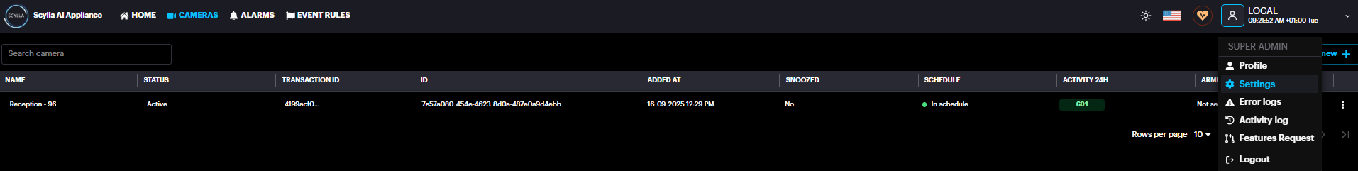
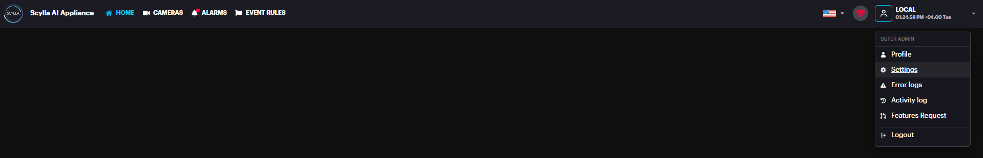
To connect Scylla Asteria™ Vanguard with the Cloud Dashboard, click the Settings from the Profile Menu
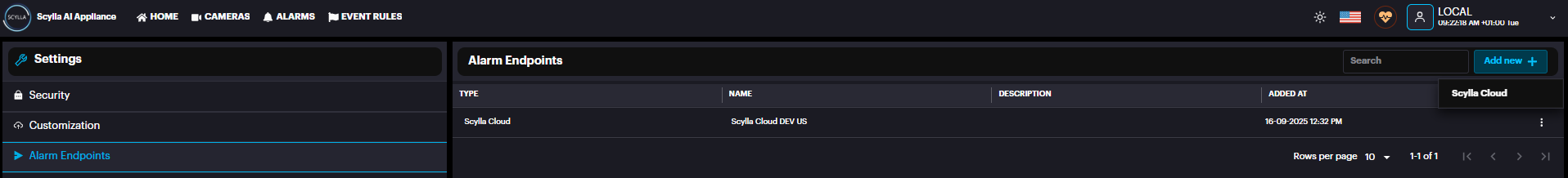
Now go to Alarm Endpoints settings and click Add new + → Scylla Cloud
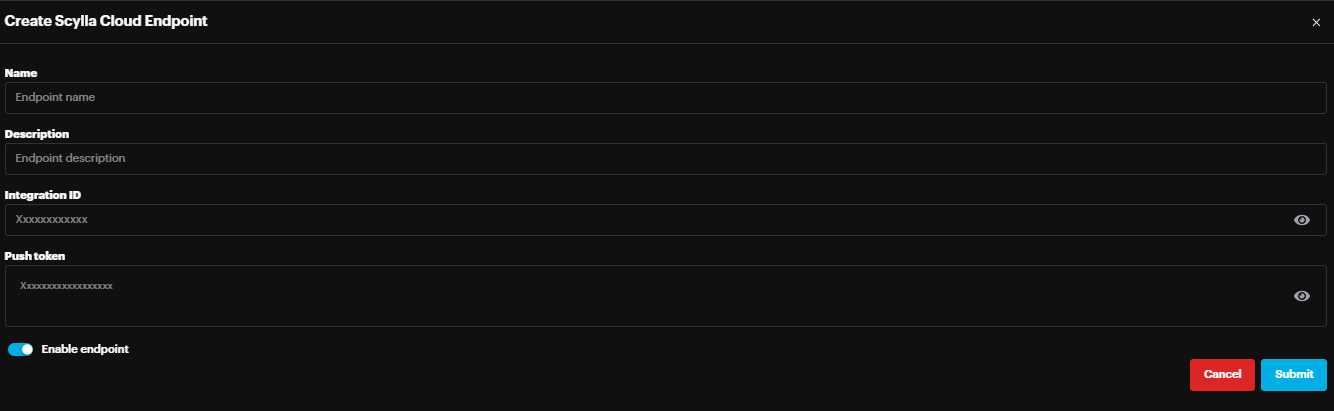
In the Endpoint Create Scylla Cloud Endpoint window, enter the Name, Integration ID, Push Token and Priority. Integration ID & Push token are obtained from the Scylla Dashboard as shown in Creating Integration section below.
Toggle the Enable endpoint to enable this endpoint
Click Submit.
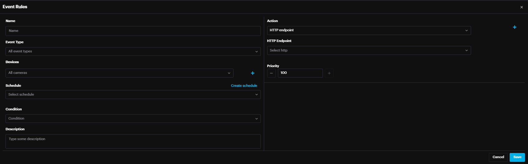
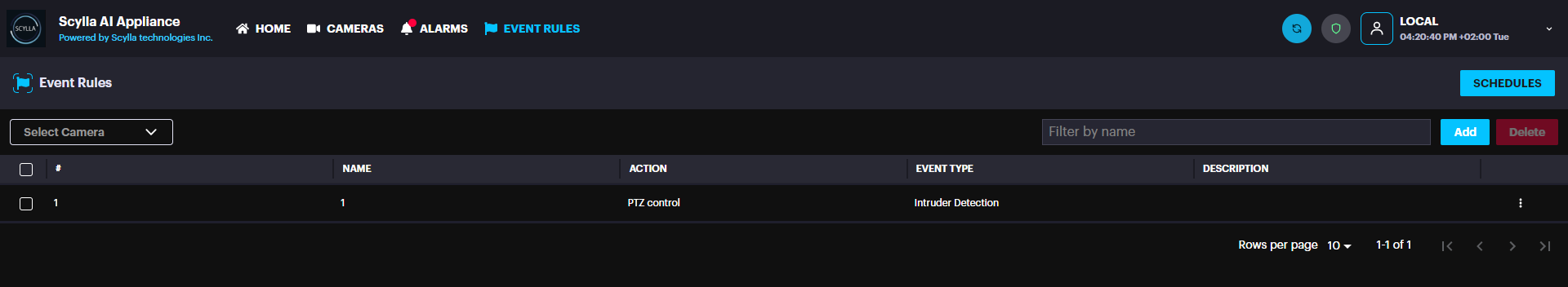
Now go to Event Rules page
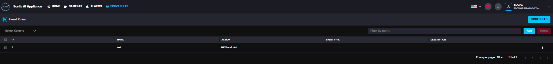
Click Add button
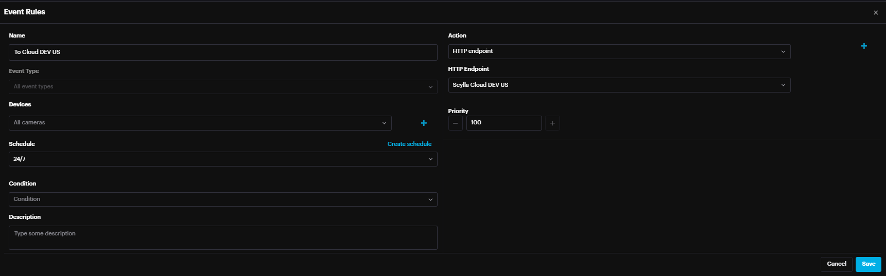
Enter Name, Event Type, Select the Camera(s), and the Area(s) drawn, Select or Create schedule, Select HTTP Endpoint as Action & Select “Scylla Cloud” created in the Alarm Endpoints earlier as the HTTP Endpoint.
Click Save.

Scylla Cloud Dashboard
Creating Integration on Cloud for Box Sync
First, you need to create or edit a location.
To create a location, log in to the dashboard.
Then go to the Sites tab from your dashboard.
On the Sites page click Add new site button.

![]()
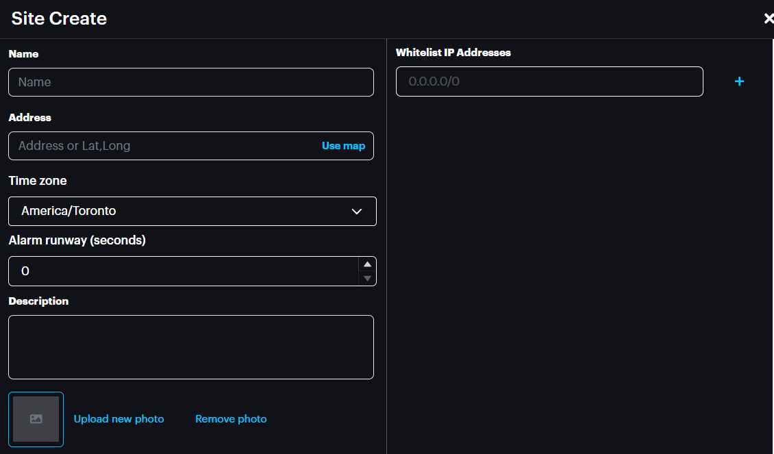
Enter the information into the corresponding fields and click Submit to save.
You can also delete the location by clicking the Delete button.
Manage Devices
On the Site page select the desired site from the left-hand list, then click on Manage Devices on the Routes window.

On the Manage Devices menu you can open the existing camera groups to see all cameras and be able to change their settings.
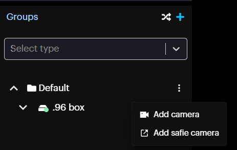
Create Group
![]()

In the opened Group Create pop-up specify the name for a new group and click Submit.

Add New Device
To add new device, click on the More Options button on the desired group and click Add camera.
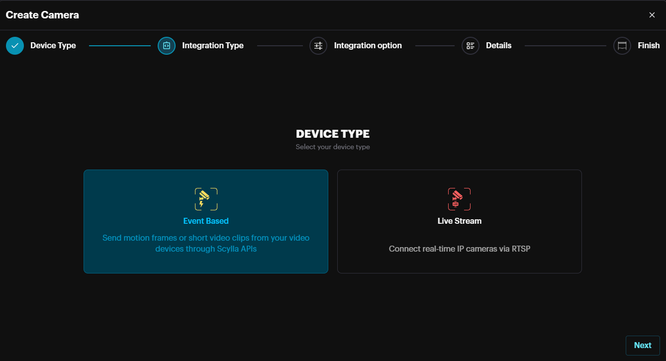
Then on the pop-up menu in the Device Type section select the Event Based and Click Next.
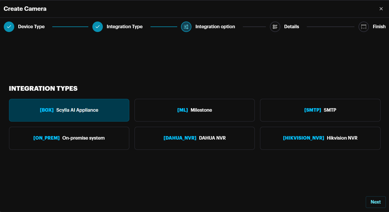
In the Integration Type section select the desired integration type (Scylla Box) and click Next.
In the Integration Option section, click the Resources button to download the manual for this integration. Then click Create.
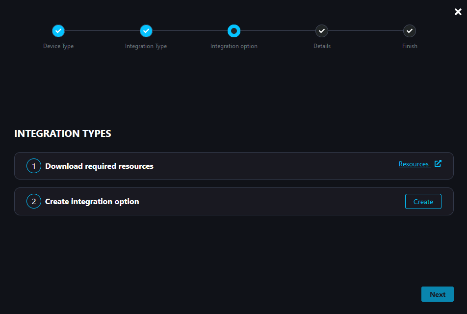
On the Create Device pop-up enter the name for the device and click Create & Continue.
Then click Next
Graphical user interface, text
Description automatically generated
In the Details section you can see the Push Token, and integration ID, which should be copied to Alarm Endpoint page on Asteria. Click Next
A screenshot of a computer
AI-generated content may be incorrect.
Click Done to finish the camera creation process.
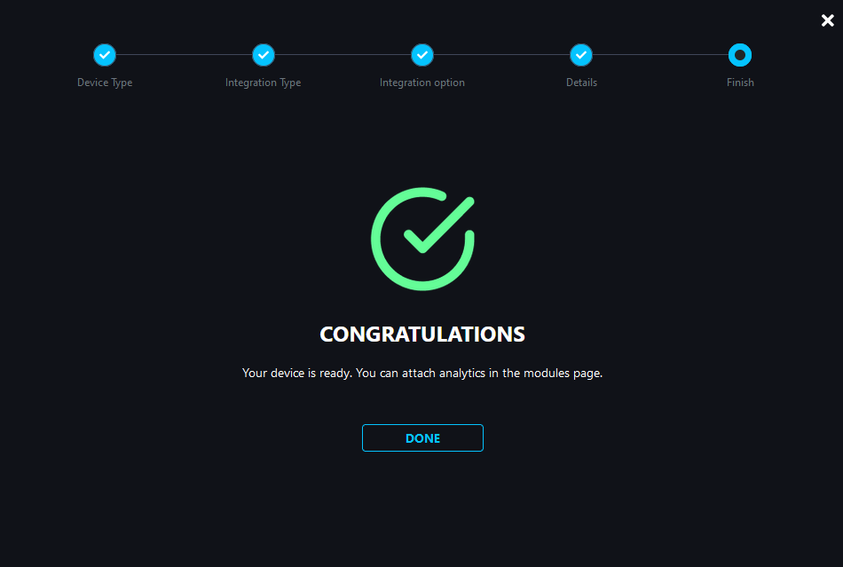
Your Asteria Vanguard is now synced with the cloud dashboard, allowing you to manage it completely from any location.
All alarms from your Vanguard device are also accessible on the cloud dashboard. You can view live, pre-event, and post-event footage to get a full picture of any activity.
Asteria Vanguard Remote Management from Cloud
You can manage Asteria devices directly from your cloud account.
To do this, log in to your cloud account and navigate to the Hardware page, then go to the Integration Drivers tab.
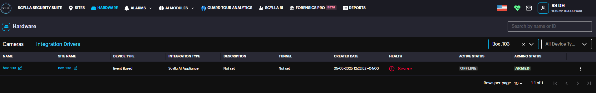
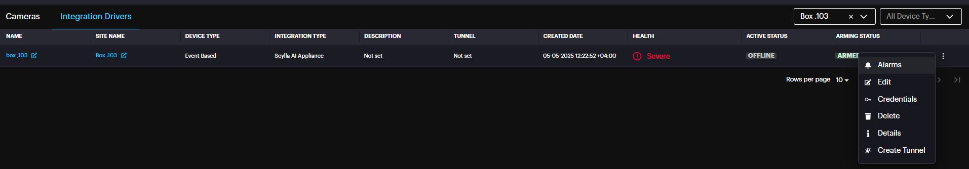
Next, click on the three-dot menu and select Create Tunnel.
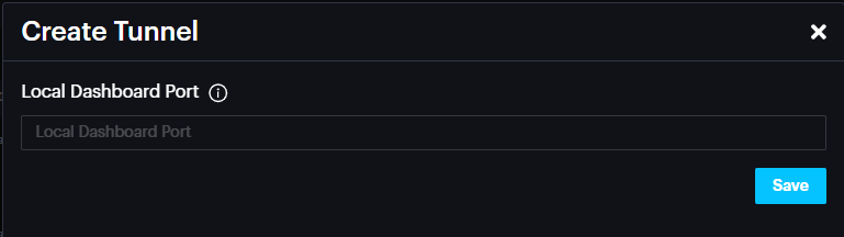
A window will appear prompting you to enter the port number for tunnel creation. By default, port 80 is used. If the port has been changed on the Asteria device, you must enter the same port here. If left blank, port 80 will be used automatically.
This action will create a tunnel, and the corresponding URL will appear under the Tunnel column.
Please note that the tunnel will remain active for 1 hour.
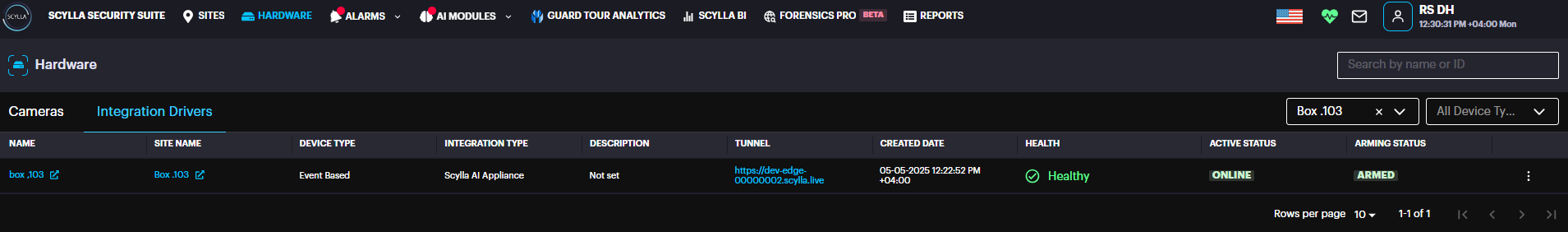
When you hover your mouse over the tunnel URL, a message appears indicating the expiration time.
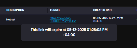
Click on the Tunnel URL to open the Asteria Dashboard.
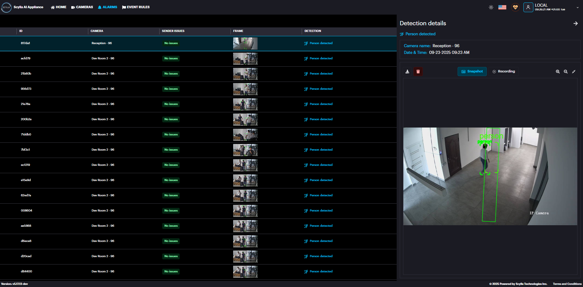
Asteria Vanguard Alarm Management from Cloud
On the Alarm Management page, you'll see alarms from your Vanguard box.
When an alarm is triggered, the left window will display a video of the detection and right window the snapshot of the detection, with the middle window displaying the alarm information.
Live Stream with Instant playback
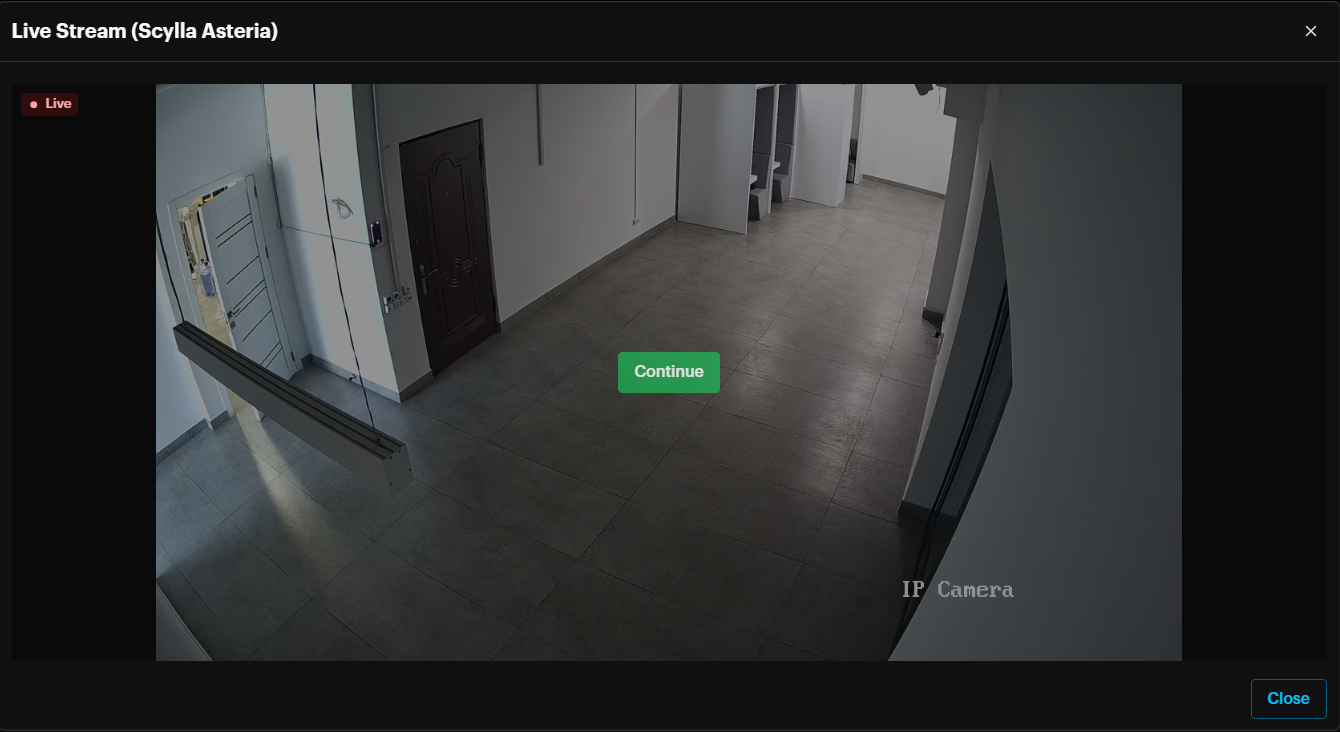
To view the camera's live stream, click the Live stream button in the left Recording window.
Live Stream window is displayed.
A screen shot of a room
AI-generated content may be incorrect.
View the live stream with a timeline of the last five minutes recording, allowing you to quickly review recent activity. It is possible to display the stream in full screen mode.
To save resources, the live stream will pause after 30 seconds of inactivity. You'll see a notification asking if you want to continue.
- Click "Continue" to keep watching the live stream. Click "Continue" to keep watching the live stream.
If there is no response after 10 seconds, the stream will automatically close.
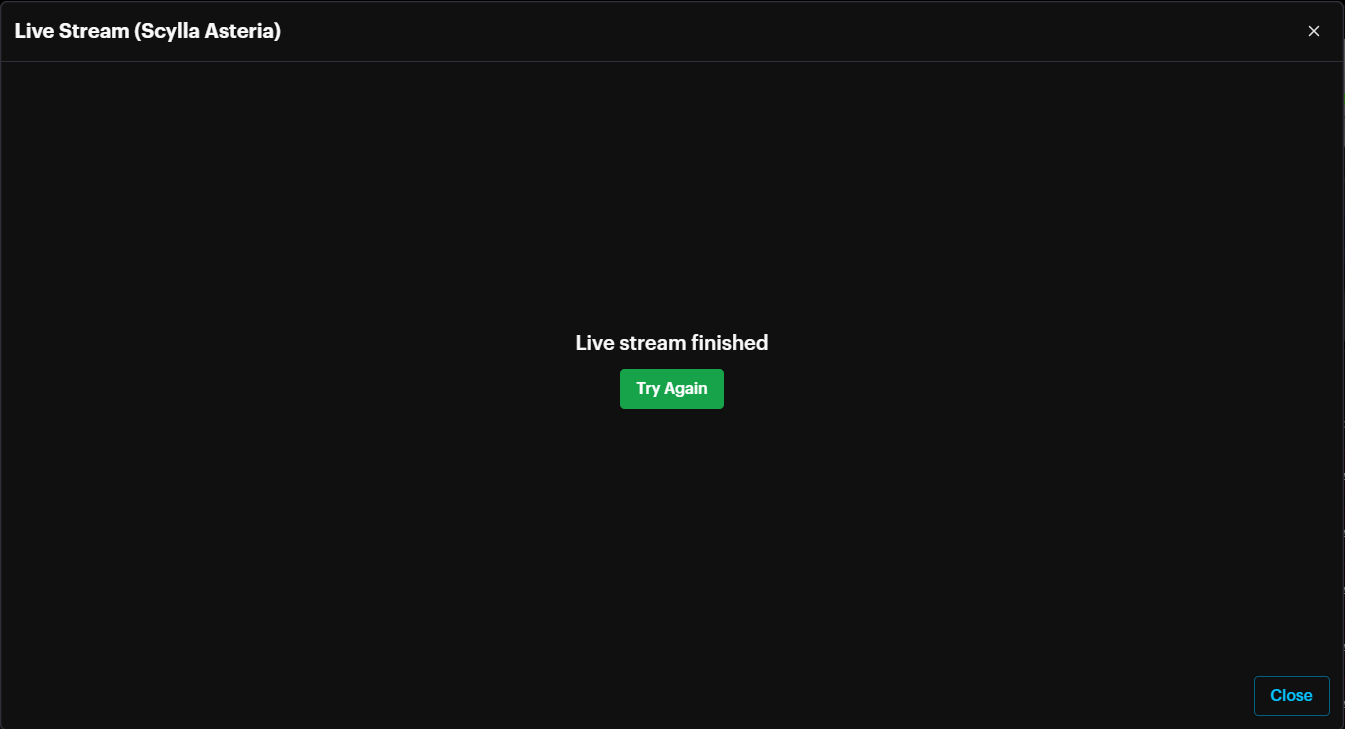
Clicking Try again will start live stream again.
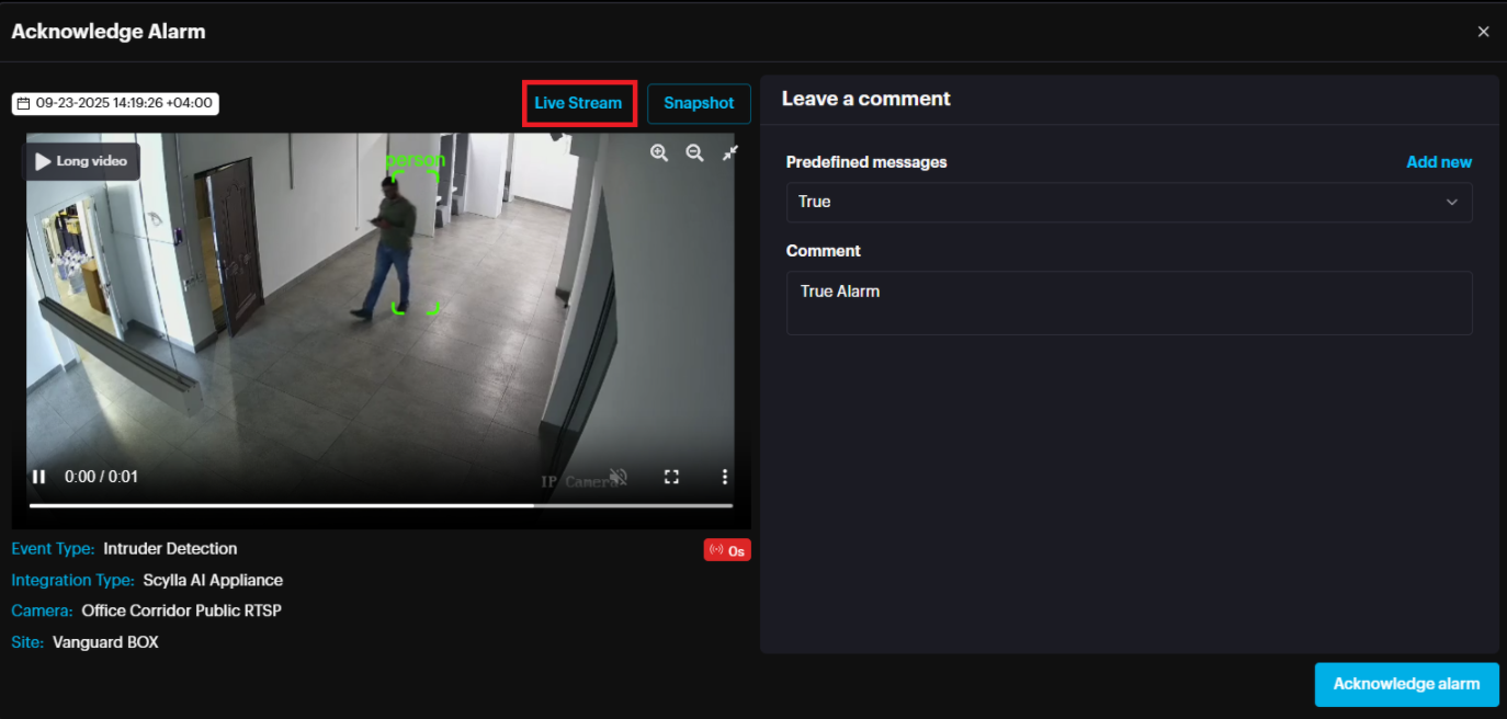
Live stream with instant playback is also displayed in the acknowledge alarm window.
Once the user clicks the acknowledge alarm button , in the acknowledge alarm window there will be the option to view the live stream with instant playback to check before acknowledging the alarm
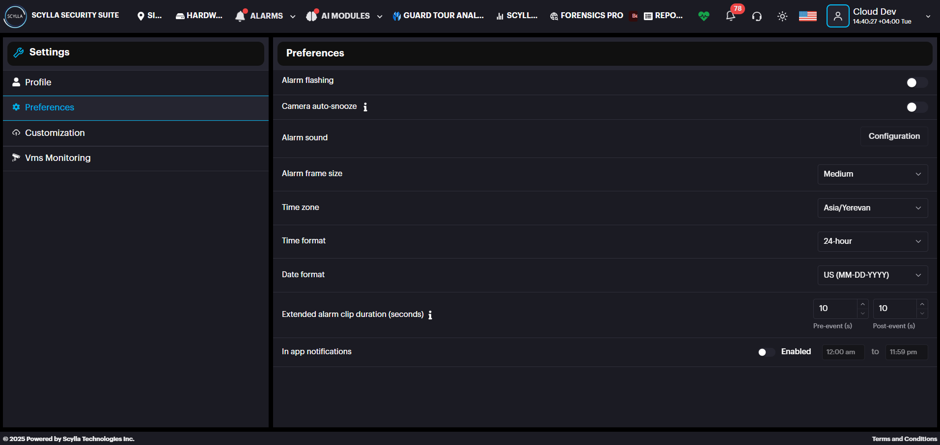
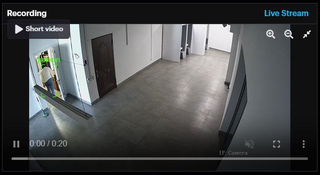
Pre/Post event alarm recording
In addition to the short detection video and snapshot, the alarm includes a longer detection video clip. This is the pre- and post-detection footage, with the length determined by your settings.
Pre- and post-detection video duration is determined from Profile PreferencesExtended alarm clip duration.
Clicking the long video button displays the pre- and post-detection video.
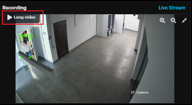
Long video can be accessed from the Alarm History page too.
Alarms on Box local Dashboard
In the ALARMS tab, you can view, download, or delete alarms. New alarms automatically appear at the top of the list.
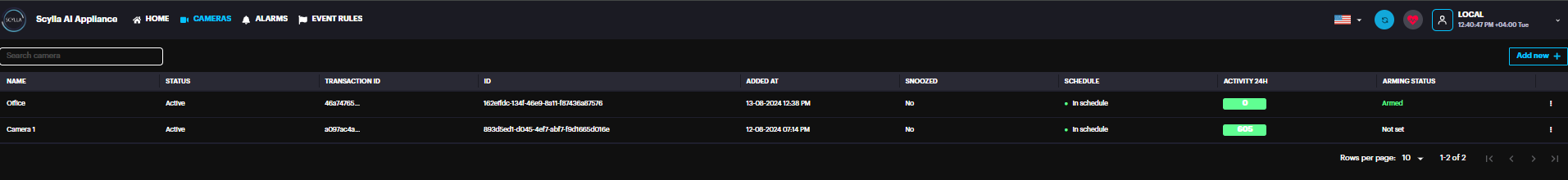
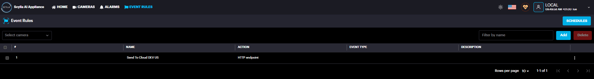
Event Rules
Navigate to Event Rules page on the top.
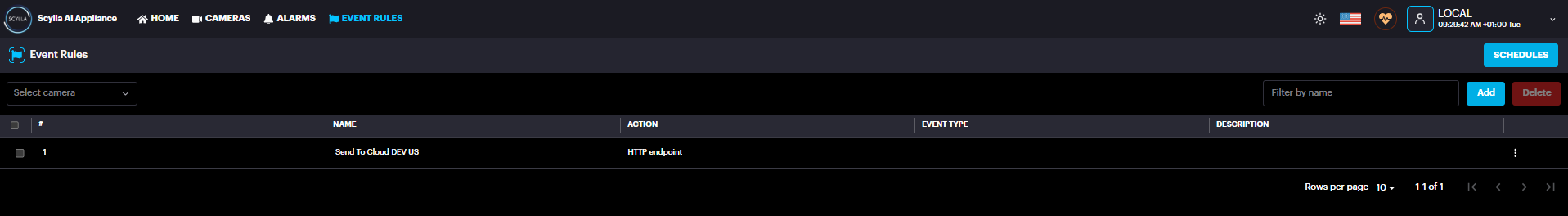
Event Rules allow users define a rule by selecting the device(s), schedule, and conditions. When these conditions are met, the rule will trigger an action, such as syncing with the cloud or activating an output.
To add an event rule click the Add button
Event Rules configuration window shows up.
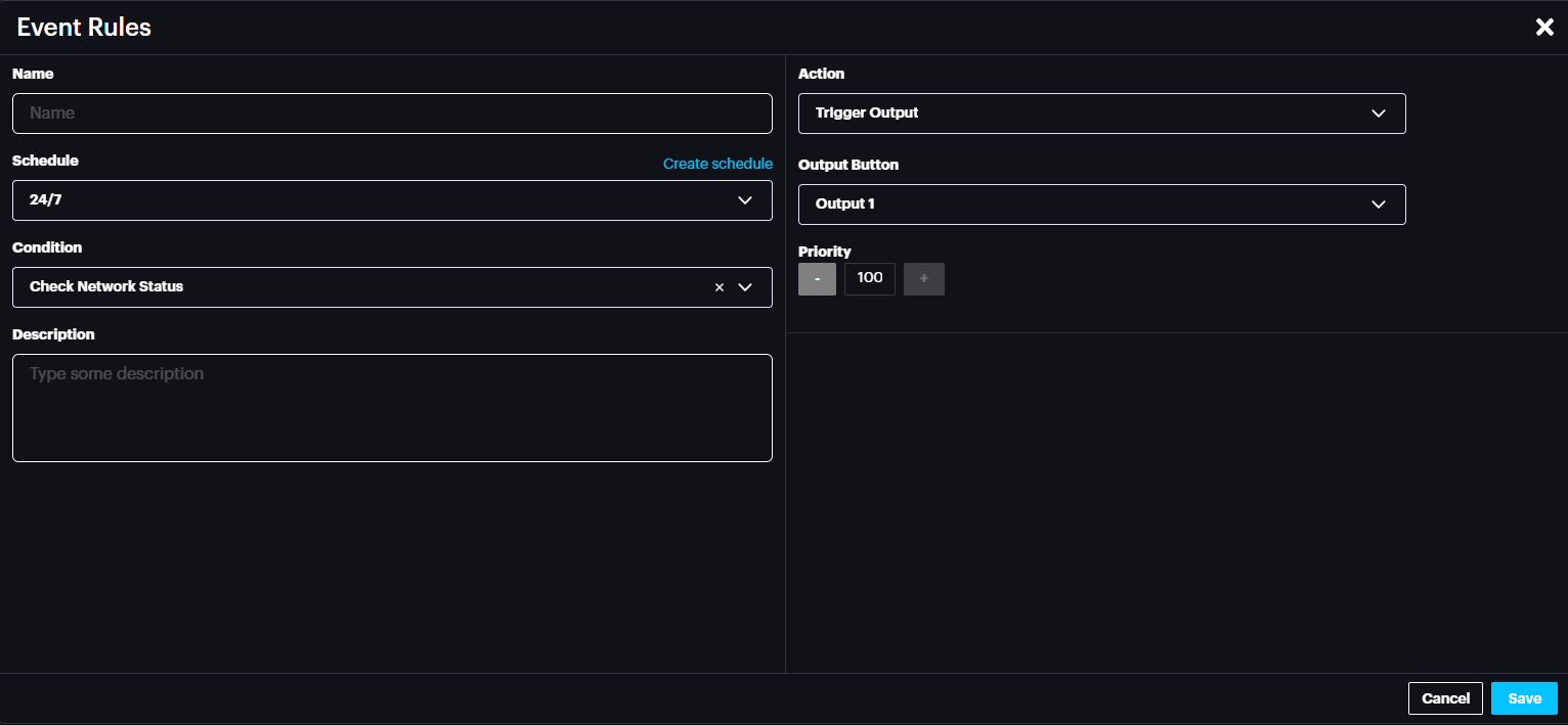
Connection Loss Output Trigger
If the Asteria device loses its internet connection, you can configure it to activate one of its alarm outputs.
To set this up:
- Select the Condition as Check Network Status.
- Under Actions, choose the Output you want to trigger.
- Click Save Select the Condition as Check Network Status.
Under Actions, choose the Output you want to trigger.
Click Save
Note: The Asteria device checks its internet connection every 60 seconds. Once the connection is restored, the triggered output will automatically return to its normal state.
Alarm Input Configuration
Digital input side accepts signals between 12-24V (rated for 2.25mA). So, you should have a circuitry as in the schematic below for Switch button. 12V, 1A is recommended.
A diagram of a switch button
Description automatically generated with low confidence
Arm/Disarm Asteria Device
Inputs such as switch button can be used to Arm/Disarm the Asteria device.
Go to Settings from the drop-down menu
Go to Arm/Disarm setting
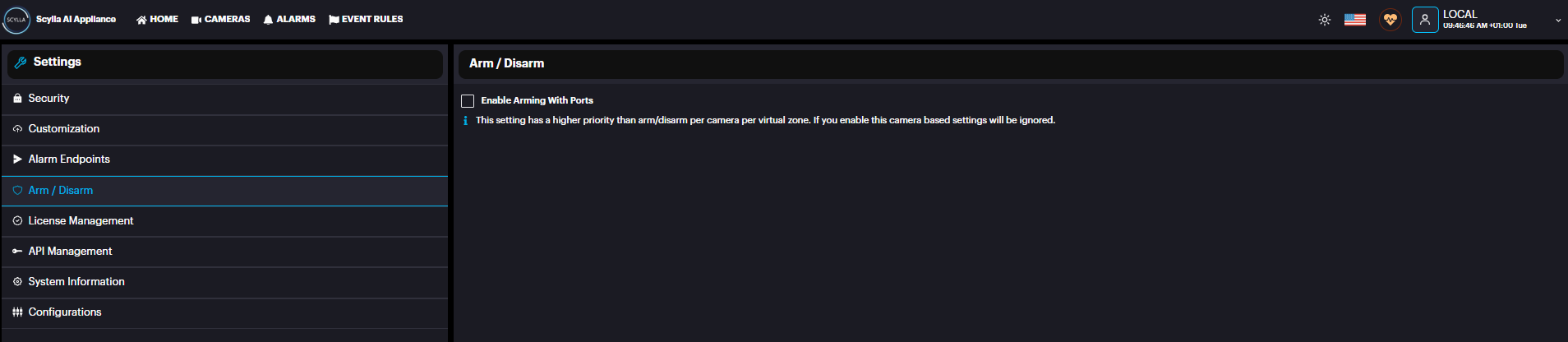
Enable the Enable Arming with Ports and Select the Alarm Input port where the switch button is connected and will be used to Arm/Disarm the Asteria device.
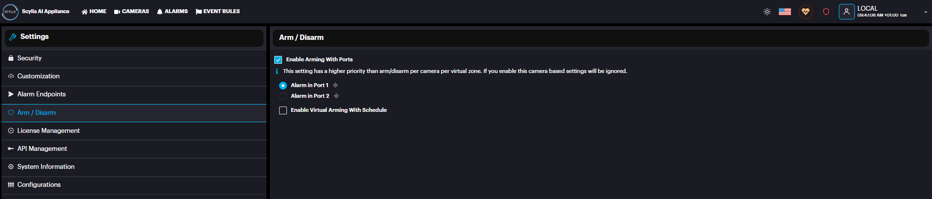
The status icon beside each port shows the status of the input
Green: The input is ON
Grey: The input is OFF
If the Asteria device is Armed, the following symbol will appear

Arm/Disarm Camera Zone
Inputs such as switch button can be used to Arm/Disarm specific Zone for a camera
To be able to configure Arm/Disarm Camera Zone, turn off device arming/disarming from the Settings page mentioned earlier.
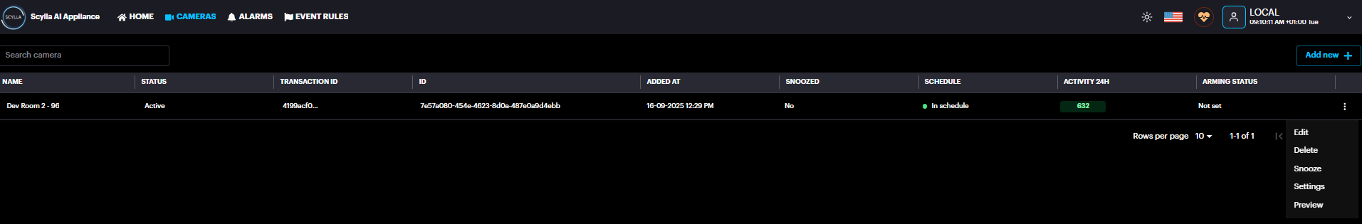
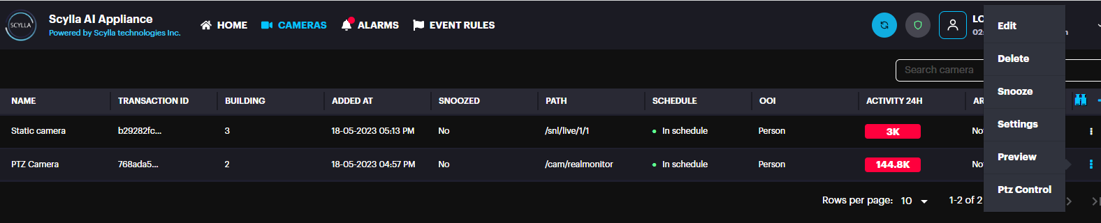
Now, Go to Cameras page
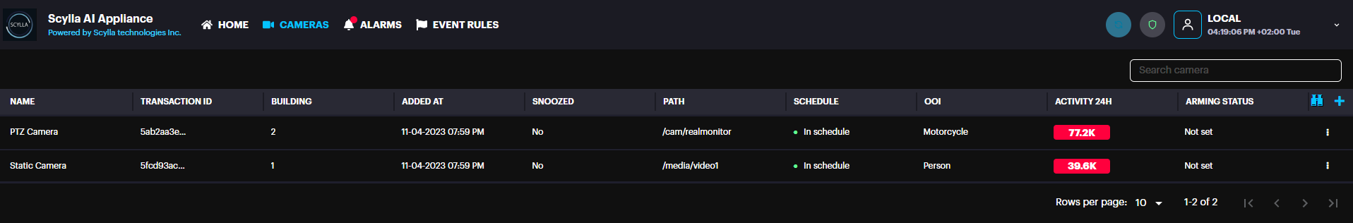
Choose the camera, Click the three dots -> Settings
Camera Settings window popups where Zones are drawn and linked to Alarm input
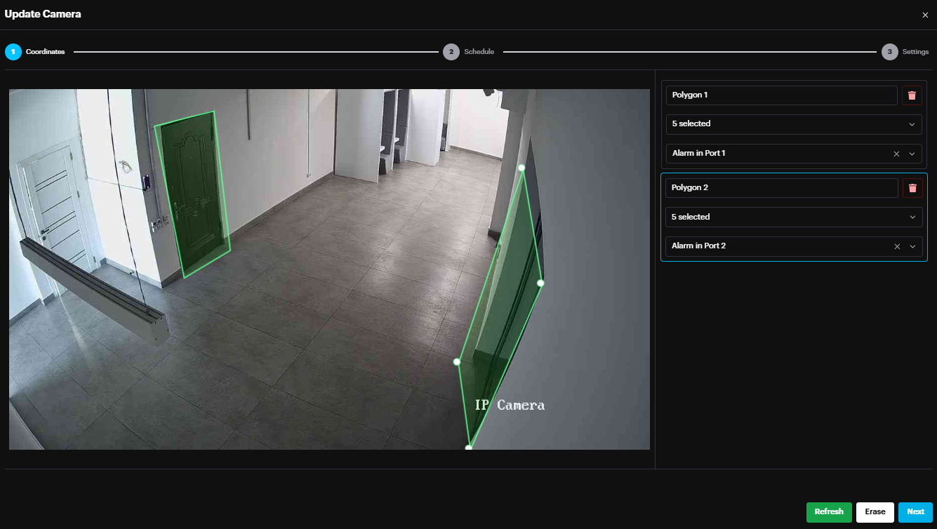
In the example above, ‘Polygon 1’ zone is linked to Alarm in Port 1.
Hence, If Alarm input Port 1 is ON, ‘Polygon 1’ zone is Armed, and alarms of this zone will appear on dashboard.
Else if Alarm input Port 1 is OFF, there are no alarms from this zone on the dashboard.
If the Alarm Input Port linked to the camera zone is ON, the Arming status Armed is shown for this camera
on the Cameras page.
After Drawing Zone(s) and linking to Input Ports, Click Next to configure the Schedule, Object of Interest and Motion Setting.
Click Apply configuration button to apply the new settings.

Alarm Output Configuration (for Vanguard Devices)
Digital output side can drive loads up to 24V and has a current limit of 1A. They work as low side switches, open-close between them and GND_ISO. So, you should have a circuitry as in the schematic below
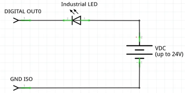
Outputs such as LED, connected to Alarm output port, can be triggered in case of alarm.
To trigger output in case of alarm, Event Rule should be created.
Go to Event Rules page
Click the Add button, to create event rule.
Event Rule configuration page popups
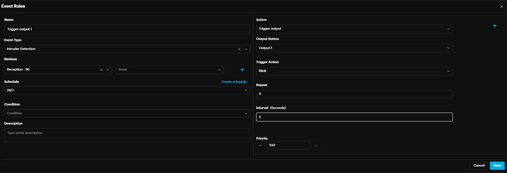
Name: Event Rule Name
Event Type: AI Module (Intruder Detection …)
Cameras: Select the Camera whose alarms will trigger the action
Schedule: Specify the schedule when the event rule is active
Action: Trigger Output
Output Button: Select the Output port/number to be triggered in case of alarm
Trigger Action:
Blink: The output is repeatedly triggered
Toggle: The output is triggered once
Note that each output button can be linked only to one camera
Click Apply configuration button to apply the new settings.
PTZ Control Configuration
To configure PTZ control, first need to configure the coordinates of PTZ / static camera.
Go to Cameras, edit the PTZ camera and click PTZ control
In the new window, PTZ live view is displayed on the left and the static camera live view on the right.
At the Bottom there are the PTZ control buttons, Static camera(s) list & Positions.
Select the Static camera from the list that will be linked to the PTZ.
There are two important points on the static camera (top right and bottom left).
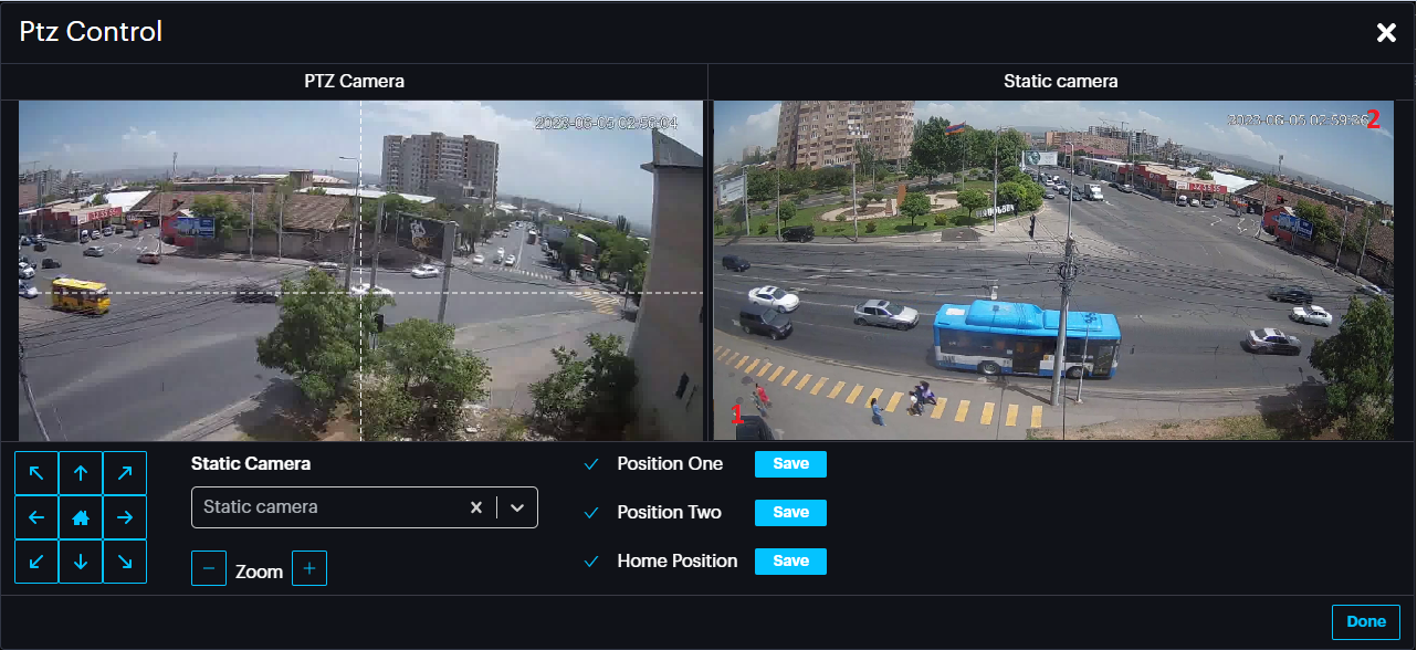
Move the PTZ so that the PTZ pointer points exactly to the Static camera’s point 1 (bottom right point).
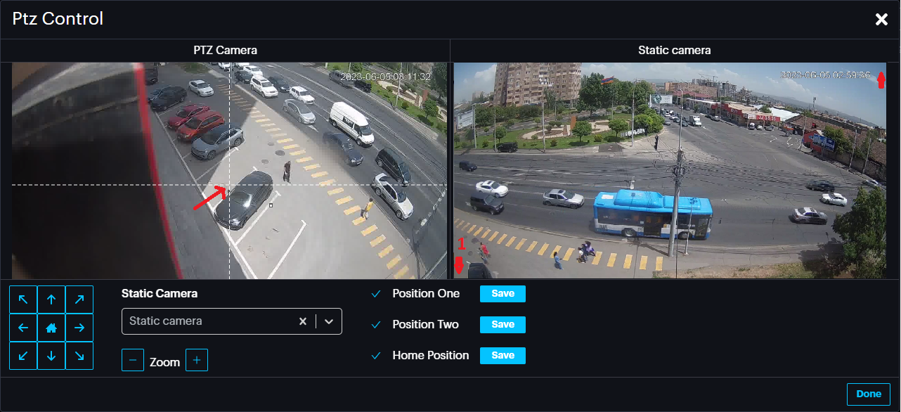
Now Click the Save button for Position One.
Repeat the same for point 2 by pointing the PTZ to the static camera’s point 2(top right point).
Then click Save button for position Two.
Finally move the PTZ camera to home position and click Save button for Home Position. This position can be specified in the event rule in case it is required for PTZ camera to always return to the same position after movement.
Click Done.
Event Rule for PTZ control
To create an event rule, go to EVENT RULES page and click Add
- Name: Name of Event Rule
- Event Type: Select the AI module, in this case Intruder Detection.
- Cameras: Select the static camera(s)
- Schedule: Select the schedule where this event rule will be active
- Action: PTZ Control
- Move action: Select either Move or Move and Zoom
- Complete action: Select Zoom out or do nothing (PTZ moves and stays in that position) or return to last position (home position specified previously).
- Interval: Specify the time after which the Complete action is triggered.
Click Save.
Profile
Preferences
In the Preferences menu to set the Time zone, Arming Status, Allow Port Queue and Restart the Asteria Box if needed.
Allow Port Queue , if enabled , allows to trigger the same alarm output from different cameras successively.
If Cam A is triggering Output 1, and at the same time Cam B is willing to trigger same output, it should wait for the Cam A to finish!
A black rectangular object with a black stripe
AI-generated content may be incorrect.
Password & Security
In the Password & Security menu change the current Login password if needed.
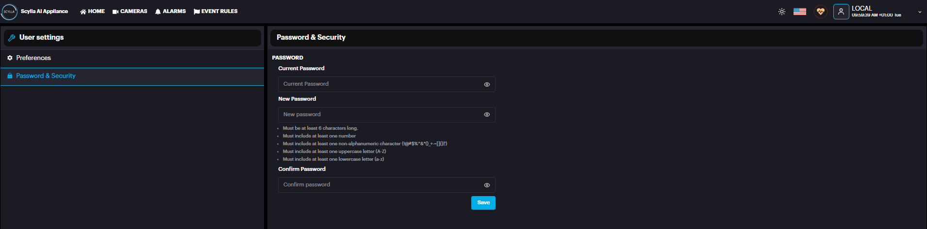
In the Security menu , set the Password complexity level and password expiration settings.
A screenshot of a computer
AI-generated content may be incorrect.
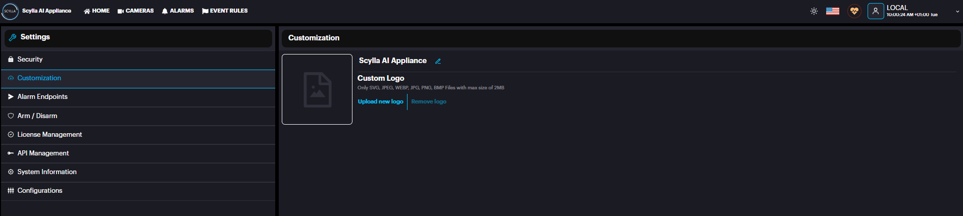
Customization
To add a custom logo, go to Customization menu and Upload New Logo.
Only JPG, JPEG, PNG, WEBP, BMP, SVG files with max size of 2MB are accepted.
Alarm endpoints
To create alarm endpoints such as Scylla cloud click Add new + , later this endpoint will be used in the event rule as an action. A screenshot of a computer AI-generated content may be incorrect.
Arm/Disarm
To enable Arming/Disarming using the alarm input ports, enable the settings, and choose the input that will be used for Arm/Disarm. The status of the input is shown next to it: green means ON and white means OFF
Integrations (Only Asteria , not Vanguard)
You can create integration with Scylla VMS or 3rd party VMS. For more information regarding a specific Integration , please contact Scylla Support.
License Management
After logging in successfully, a red banner will appear if there are no activated licenses on the Asteria device.
You can click the "Activate Now" button to be redirected to the License Management page, or navigate to the License Management page manually from Account menu → Settings → License Management.
There are two options available to activate the license: online or offline.
Click the activate button, and a window displaying two options—Online and Offline activation—will appear.
Activate Online
To activate the license online, ensure the Asteria device is connected to the internet. The only requirement is the product key (EID), which you will receive via email.
Copy the EID from the email and paste it into the Product Key (EID) field under Activate Online and press the Apply button.
A screenshot of a computer program AI-generated content may be incorrect.
After the license is successfully activated, a confirmation message will appear. Once the license is successfully activated, the license details will appear in the list below, displaying the AI module, quantity (number of cameras), and restrictions (such as an expiration date or if it is perpetual).
A screenshot of a computer
AI-generated content may be incorrect.
Click on the "Apply Configuration" button that is blinking at the top.
If the restriction is marked in red, it indicates that the license has already expired. If it is marked in orange, it means the license will expire soon.
An orange banner will appear on the dashboard 14 days prior to the license expiration date to notify the client. If the user closes the banner, it will not reappear; otherwise, it will remain visible.
The user can navigate to the License Management page to activate the renewal license or contact support@scylla.ai for assistance.
A red banner will appear on the dashboard when the license has expired.
Activate Offline
If there is no internet access, the license can be activated offline. First, download the C2V file from the activation window.
This action will download the C2V file to your device.
In the initial License email, you will find a link to access the Entitlement Management System.
Link : https://scyllaspzoo.prod.sentinelcloud.com/customer
On the EMS login page, click on the EID tab and enter the EID provided in the email and click Login.
After logging in successfully, the Entitlement page will be displayed. Click the "Activate Offline" button.
Next, click the "Select File" button to upload the C2V file that was downloaded from the Asteria device.
After successfully uploading the file, click the "Complete Activation" button.
The user has two options to download the V2C file:
-
Click the "Download License" button at the bottom. Click the "Download License" button at the bottom.
-
Download it from the email received after activation. Download it from the email received after activation.
After downloading the V2C file, transfer it to the Asteria device and upload it from the activation window.
API Management
Here you can find information and documentation for API integration with Asteria box.
First click Create Key to to create an API key.
System Information
To view the AI Module, Serial Number & Support Reference information, Go to System Information menu
A black rectangular object with a black line
AI-generated content may be incorrect.
Video Archive
It is possible to disable recording on the Asteria device. This will disable also the Live Stream functionality on the cloud dashboard.
Configurations
This menu includes configurations related to IDS module such as Thresholds, cooldown etc.
Click the Configure button in the thresholds row to open the Thresholds window.
In this section, we introduce a recent feature – thresholds – and the capability to fine-tune them. Thresholds play a crucial role in the analytical system, influencing the determination of whether a specific object qualifies as one of the objects of interest. Simply put, the AI predicts the likelihood of an object, and this probability is then compared to a set threshold. If the probability surpasses the threshold, the object is confirmed, triggering the formation of a corresponding alarm. Conversely, if the probability falls below the threshold, the object is disregarded.
To enhance the selectivity and certainty of detections, it is advisable to raise the corresponding threshold. However, if you wish to increase the detector's sensitivity, even at the expense of a higher potential for mistakes, lowering the corresponding threshold is recommended.
The same set of thresholds are applied across all cameras. So, when you change the preset value, it will affect analysis of all cameras in your system.
For each category and mode, predefined values for "sensitive," default "normal," and "selective" settings are available. It is recommended to use these values when tuning your system's performance.
You also have the option to set custom values, but it is advisable to consult Scylla Tech support beforehand.
Examples
-
If your system generates more False Positive alerts for a person during the night, you can set the IR Threshold for Person to a "selective" level. If your system generates more False Positive alerts for a person during the night, you can set the IR Threshold for Person to a "selective" level.
-
To increase the system's sensitivity and detect distant, small cars before they approach your fence (with no concern for other objects resembling cars), adjust the thresholds for all vehicles of interest to "Sensitive" in both the "Thresholds" To increase the system's sensitivity and detect distant, small cars before they approach your fence (with no concern for other objects resembling cars), adjust the thresholds for all vehicles of interest to "Sensitive" in both the "Thresholds"
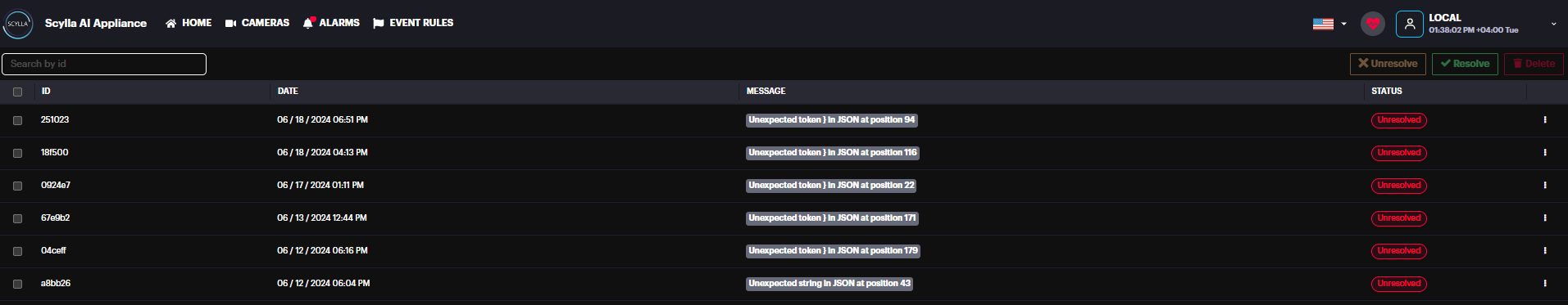
Error Logs
The error logs will display the error date, error message, and provide an option to mark the error as resolved.
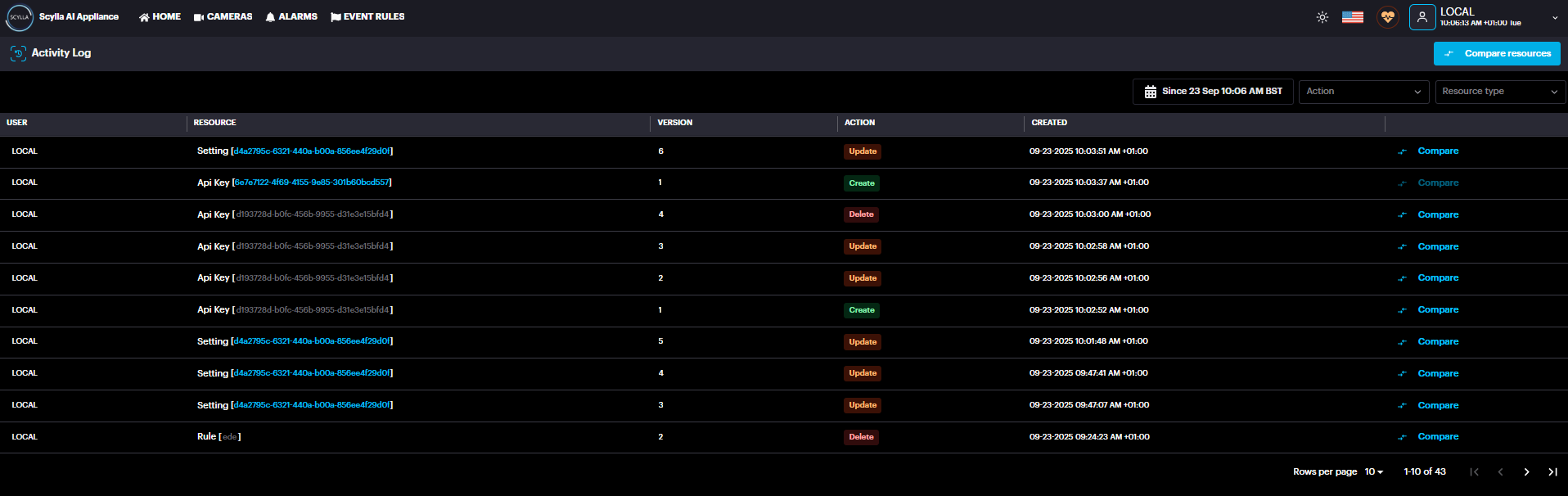
Activity Logs
The Activity Logs page displays a list of Asteria activities, providing details such as the User, Resource, and Action associated with each activity.
Scylla AI Mobile Application
Whether you're an iOS or Android user, now you have a cutting-edge tool at your disposal that allows you to identify potential threats or anomalies swiftly and efficiently. The app's intuitive interface guarantees a smooth experience, ensuring easy management of all your sites and cameras.
The Scylla AI mobile app allows you to fully manage and monitor your Asteria boxes.
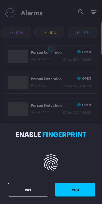
Login

Upon launching the mobile application, you will be prompted for a workspace ID (optional) which is optional code assigned by Scylla for your organization. If you don’t have one, simply leave this field blank . Click Continue. On the Login page , enter your login details. Please provide your cloud account credentials to proceed. Accept the terms and click SIGN IN. After successful login , you will be given the option to enable fingerprint login for future access.
Alarms
Upon successful login, the Alarms page will be displayed, showing all alarms associated with your account.
![]()
Clicking an alarm opens Alarm Details, where you can:
- View the detection snapshot and video with bounding boxes.
- Access the live stream.
- Change the alarm Status (Acknowledge, Dismiss, False).
- Share the alarm via a copied link or email. View the detection snapshot and video with bounding boxes.
Access the live stream. Change the alarm Status (Acknowledge, Dismiss, False). Share the alarm via a copied link or email.
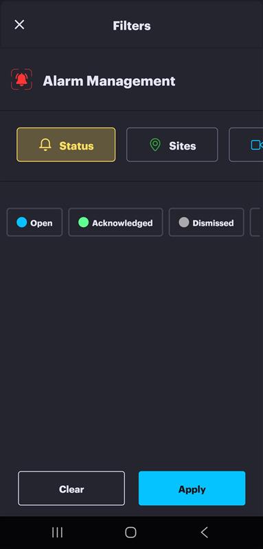
Filtering options are available at the top of the screen to help you quickly locate specific alarms.
Methods for Filtering:
- Quick Filter (AI Module): Select a specific AI Module shown at the top of the list for immediate results.
- Advanced Filtering: Click the Filters button (located in the top-right corner) to access detailed criteria. You can refine your search based on:
- Sites
- Cameras
- Labels
- Date/Time Range
- Status
Quick Filter (AI Module): Select a specific AI Module shown at the top of the list for immediate results.
Advanced Filtering: Click the Filters button (located in the top-right corner) to access detailed criteria. You can refine your search based on:
- Sites
- Cameras
- Labels
- Date/Time Range
- Status
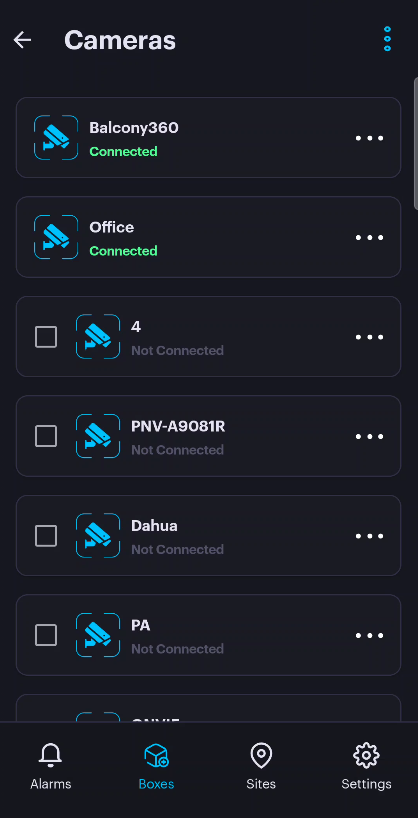
Boxes
When you navigate to the "Boxes" menu, all devices connected to the network will be displayed automatically.
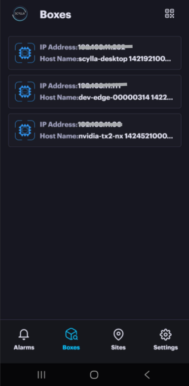
Select the desired box. For new devices, the app will attempt to log in automatically using the default credentials (admin/admin).
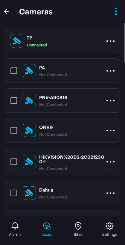
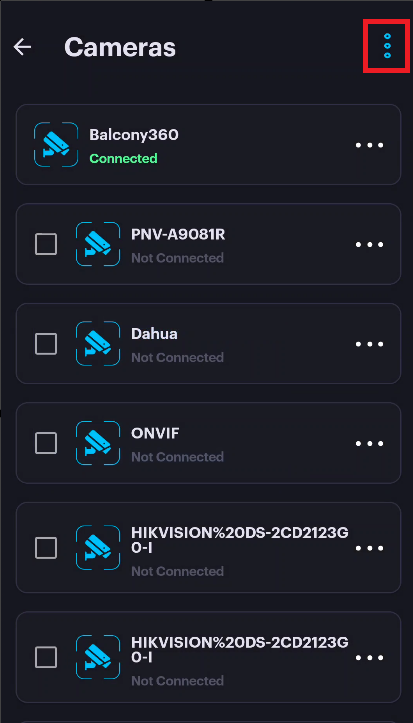
A list of both connected and not connected cameras to the box is displayed.
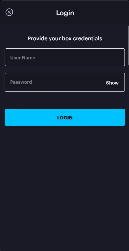
Note: If the box password has already been changed, the app will prompt you to enter the new password. Once provided, the app will save it for future logins.
Cameras
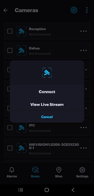
Connect Discovered Camera(s)
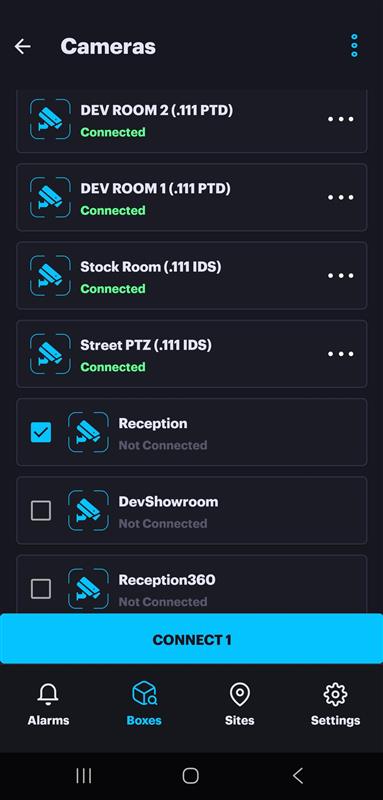
Choose the camera from the list that you wish to connect to the box, and then click "Connect."
You will be prompted to enter the camera credentials, along with an optional description.
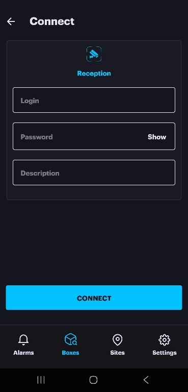
After successfully entering the camera credentials and establishing the connection, a popup message will appear .Click Done.
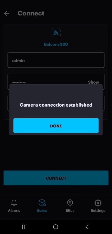
The camera will now display a connected status and is ready for you to access its settings.
Note: For the Not Connected cameras it is possible to View Live Stream after entering the camera credentials.
After establishing camera connections and making any necessary adjustments to the settings, the Apply Configuration button will become visible at the top of the page.
To save and activate your changes, click the Apply Configuration button.
Add camera(s) manually
To add a camera manually, click More Options at the top and select Add Camera.
Enter camera name , camera URL and ONVIF port (if applicable) and click Connect.
If successfully connected , camera frame appears with option to change name & URL before connecting. Once done click Connect. A pop up message appears . Click DONE.
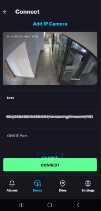
The camera is now connected to the box.
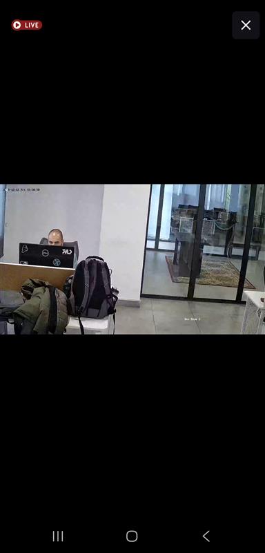
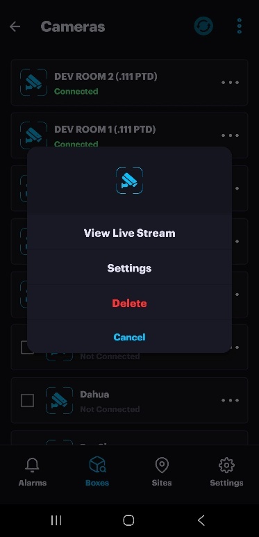
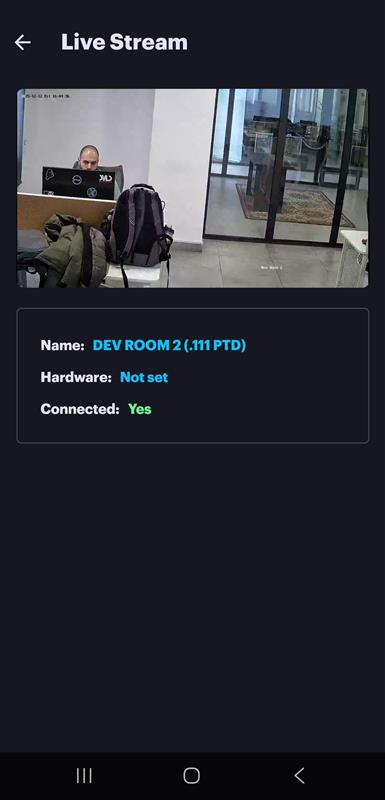
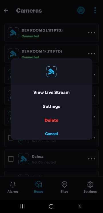
View Live Stream
Click "View Live Stream" to access the camera's live stream along with additional information.
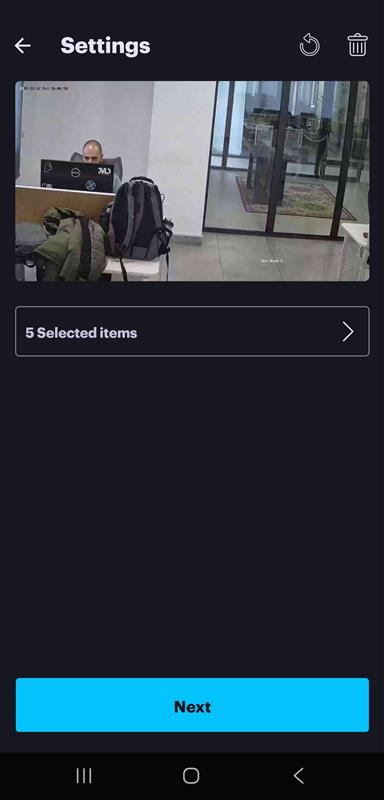
Camera Settings
Return to the camera page, click on More Options next to the camera, and select Settings.
A frame from the camera is retrieved and displayed, allowing the user to draw active area(s) or zone(s).
Next, the user can click on the "Object of Interest" dropdown menu to select the desired OOI to be detected. Then click Done.
Alarm input ports can be utilized to arm or disarm an active area or zone. In this case, the user must specify the arming port from the dropdown menu; otherwise, leave it empty.
Now click Next
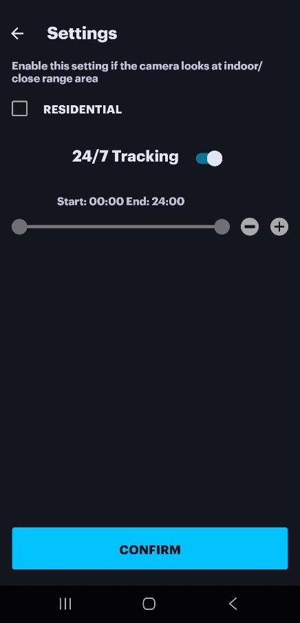
Here, the user has the option to enable the residential setting and configure the schedule.
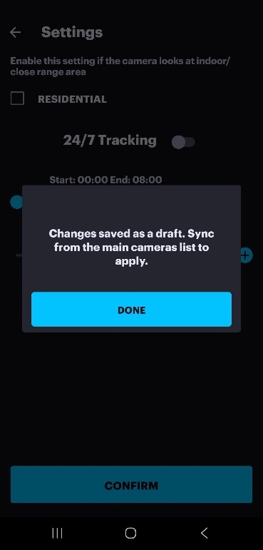
Click CONFIRM. A pop up window requiring to Sync configuration to Asteria from the camera list page. Click the Sync button and click OK.
Box Settings
To access the box settings, go to More Options at the top of the page and then click on Box Settings.
To enable arming or disarming of the box through alarm input ports, click Enable Arming with Ports and select the desired port. Click DONE. Click OK.
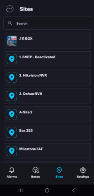
Sites
The Sites page provides tools to manage the operational status of your locations and individual cameras.
- Site Management: You can Snooze or Disarm an entire site.
- Camera Management: You can also Snooze or Disarm specific cameras within a site. Site Management: You can Snooze or Disarm an entire site.
Camera Management: You can also Snooze or Disarm specific cameras within a site.
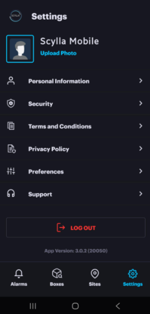
Settings
The Settings page allows you to manage and configure various aspects of your account and application behavior. This page contains the following sections:
- Personal Information: Manage your account details and profile information.
- Security Settings: Configure security options (e.g., password, two-factor authentication).
- Terms and Conditions: Review the service agreement.
- Privacy Policy: Review how your data is handled.
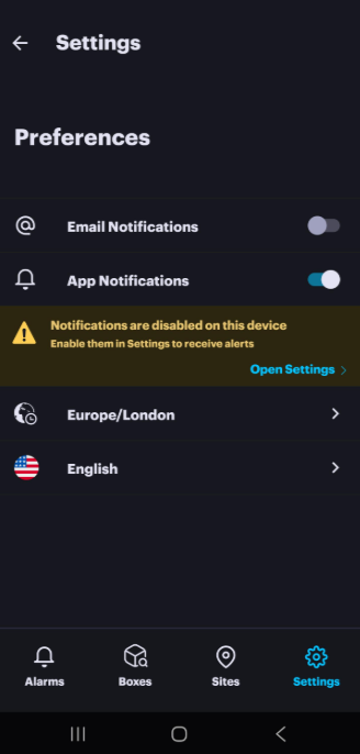
- Preferences: Adjust application-specific settings such as language , notification and timezone
- Support: Access help resources and contact support. Personal Information: Manage your account details and profile information.
Security Settings: Configure security options (e.g., password, two-factor authentication).
Terms and Conditions: Review the service agreement.
Privacy Policy: Review how your data is handled.
Preferences: Adjust application-specific settings such as language , notification and timezone
Support: Access help resources and contact support.
Note: For iOS devices it is possible to enable the Critical Alerts to bypass mute and Do Not Disturb.
We value and appreciate your feedback. If you have any questions or suggestions, please contact support@scylla.ai or submit a request to the Scylla Help Center at https://support.scylla.ai/portal/en/home.